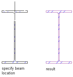
Use this procedure to insert detail components that may need to be depicted multiple times at a particular orientation, such as nails or screws. In this example, the tool for inserting a steel beam has the View property set to Section.
- Activate the detail component insertion tool for the component.
- Click an insertion point in the drawing area to insert the component at the default orientation, or select one of the following options:
If you want to… Then… specify a different base point enter b (for Base point), select the new base point, and press Enter to insert the component using the new base point. change the default orientation angle of the component enter r (for Rotate), and then either enter the number of degrees to rotate the component in a counterclockwise direction, or manually rotate the component to the desired angle and click to set the new orientation. Click again to insert the component at the specified angle. flip the component along its X axis enter x (for Xflip), and click to insert the component. flip the component along its Y axis enter y (for Yflip), and click to insert the component. - Click elsewhere in the drawing area to “stamp” additional copies of the component, either at the default orientation or as specified in Step 2.

Steel beam component inserted at default orientation