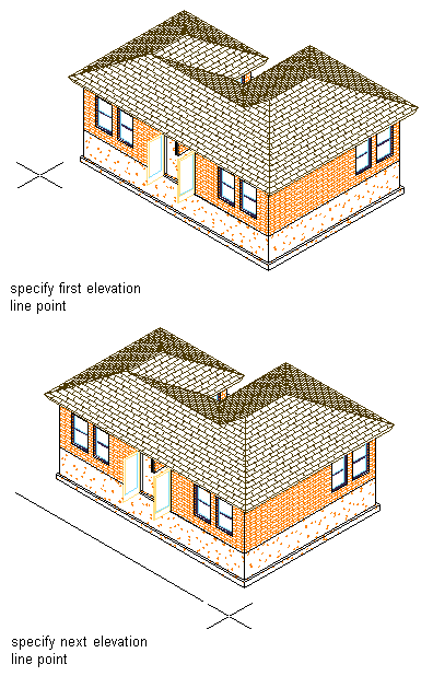
Use this procedure to draw an elevation line with an elevation mark at each end. You draw an elevation line by specifying a start point and an endpoint for the line in relation to your building model.
- Click
 .
. 
- Specify the elevation line start point. Note: Specify the start point and endpoint for the elevation line so that it extends past the face or segment of your building model view, thus ensuring that all objects are included in the elevation view.
- Specify the elevation line endpoint.
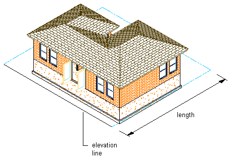
The elevation line is displayed in your drawing with an elevation mark. The elevation line boundary is drawn using the elevation line as its left side and forming a box with the elevation line. This is the area that defines the elevation.
Drawing an elevation line in 3D view
Drawing an elevation line in 3D view
Depending on the direction in which you drew the elevation line, the elevation mark points in the direction of the elevation view.
The elevation mark is a multi-view block, anchored to the elevation line. You can edit the elevation mark to change the information that is displayed in the bubble.
Once you have an elevation line in your drawing, you can change the properties of the line to change the elevation.