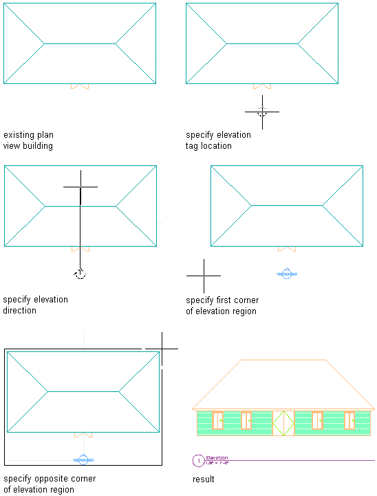
The first step in creating elevations is to draw an elevation line relative to your building model. The elevation line defines the extents of the elevation view of the building model.
Creating an Elevation Object from an Elevation Line
When you generate an elevation from an elevation line, you specify the type of elevation object that is created.
| When you create… | The result is… |
|---|---|
| a 2D elevation object | an orthographic projection from the building model. |
| a 3D elevation object | the area of the building model defined in the elevation line. |
Viewing the Elevation Line
In plan view, the elevation line is displayed as you would expect on a construction document.
Creating an Elevation
In an isometric view, the same elevation line is displayed with a boundary that defines the depth of elevation view.
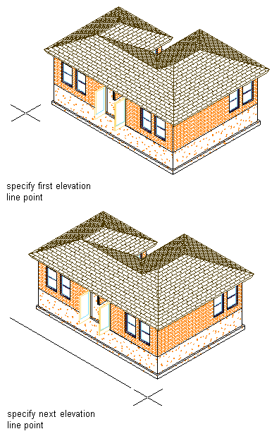
Drawing an elevation line in 3D view
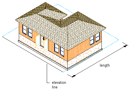
Resulting elevation line in 3D view
Changing the Elevation Line
You can change the elevation line to control the elevation that you create. Using the elevation line’s grips, you can change the height and shape of the elevation. You can also add a lower extension to the elevation and create elevation subdivisions.
You can change elevation line properties before you create an elevation. You can also change elevation line properties and update an elevation that you have already created.
Using Subdivisions in Elevations
You can set up graphic subdivisions in elevation line properties. These subdivisions are then added to the 2D or 3D elevation you create. Subdivisions are specified at distances from the elevation line. You can control the lineweight and other display properties of subdivisions to add levels of depth to elevations. For example, you can display one subdivision with a heavy lineweight and another subdivision with a lighter lineweight to suggest that the first subdivision is in front of the second subdivision.