Customize the shape of the parts lists by creating a custom parts list using blocks.
Custom parts lists require at least two blocks: one block for the parts list heading row, and another for the body row. If necessary, you can have several blocks for the body row. The heading block and the body blocks must have the same name, with a digit at the end to differentiate them.
The heading block usually contains a frame with a heading text or attribute inside. The name of the heading block ends with the digit 0. For example MYPLIST0 is a valid name for the heading block.
The body blocks become a template for one parts list row. The name of the first body block must end with the digit 1, the second body block must end with the digit 2, and so on. For example, MYPLIST1 and MYPLIST2 are valid body block names for the heading block MYPLIST0.
Body blocks usually contain the frame for a row and attributes that indicate which component property they show. Set the tag name of the attribute to the name of the property to show. For example, if the Body block shows the component property Material, name the attribute tag MATERIAL.
One limitation of using the component property name as the attribute tag is that there is no mechanism to fit text within the space reserved for it. For example, if you use DESCRIPTION as the tag name and reserve a column width of 35 for it, if the description of an item in the parts lists exceeds 35, it will overflow to the next column. To work around this issue, use the internal representation.
The internal representation takes the form #GENST{#}, where #GENST is the Component Property ID and {#} is a number to indicate text fit. For example, the Component Property ID for DESCRIPTION is 5GENST (See the topic Component Property Id Reference for full list). If the available space for the description is 35 and the text height is 3.5, divide the available space (35) by the text height (3.5), enter the resulting value (10) between curly brackets, and append it to the Component Property ID (5GENST{10}, in this case). If the description of an item exceeds 35 in width, the text compresses to fit into the available space.
You can create the heading block and the body blocks in the current drawing or in an external drawing. If you use an external drawing, the drawing must have the same name as the blocks. For example, the file containing the parts list blocks MYPLIST0, MYPLIST1, and MYPLIST2 must be saved as myplist.dwg.
After you create the blocks for the custom parts list, you can configure the system to use the custom parts list as the default parts list style. You can also set up whether the heading row appears at the top of the parts list or at the bottom and set up column splitting. For more information on the heading row position and column splitting, refer to Configuring standard-based parts lists.
Additional, the system enables you to keep standard style parts lists as well as custom style parts lists in the same drawing. You can select the parts list style when you create the parts list.
See an example...
The following image shows an example of the heading block MYPLIST0.

The following image shows an example of the first body block, MYPLIST1. Property IDs identify the component properties that appear in the row.

The following image shows an example of the second body block, MYPLIST2. Property IDs identify the component properties. They overlap because of their close proximity.

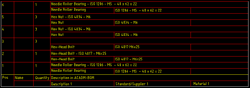
The following image shows a sample parts list based on the blocks. The data rows derive from the body blocks. The data row based on MYPLIST2 stacks on top of the data row based on MYPLIST1.

The Position and Summation sub folders of the MSK folder contain sample drawings containing blocks for custom parts lists. The blocks in these drawings contain translatable text (the samples work in all languages) in the heading block, which takes the form (genmsg “gendwg” 37){27.5}. If you implement a custom parts list, do not concern yourself with translatable text. Type the text directly.