When you select the drafting standard, the default settings for parts lists change to match that drafting standard.
If necessary, you can customize these settings to suit your drafting requirements.
Configuring a parts list involves:
- Specifying which columns appear in parts lists.
In parts lists, each column corresponds to a component property, so each column behaves in accordance to the settings of the component property. For example, the caption, data type, and precision set in the component properties are the same for the corresponding parts list column.
Note: When you add a component property to a parts list, it appears in the BOM automatically. - Formatting parts list columns.
After you add columns to a parts list, you can set the width of each column. You can also specify the alignment of the column header and the data rows.
The order in which component properties appear in the Parts List tab of the BOM Settings dialog box is the order in which the columns appear in parts lists. Use the Move Up and Move Down buttons to change the order in which columns appear.
- Setting up the layout of parts lists.
You can set the visibility of the parts list title and column heading. You can specify whether they appear at the top or at the bottom of the parts list. You can set up the row and column margins for the heading row and data rows separately. You can select whether a grip frame appears, enabling grip editing in the drawing area.
- Configuring parts list text options.
Because text and leader lines are the most common objects used for annotations, AutoCAD Mechanical toolset provides a single configuration point (the Standard Settings dialog box) enabling you to specify their default properties. These settings are the master settings.
When the text size for the parts list is “By NameOfCurrentDraftingStandard,” it acquires the base height master setting automatically. If you modify the master settings, the text size for parts lists automatically updates. If you do not want the text size for parts lists to follow the master settings, you can override the setting to a specific value.
You can also configure how text appears within a parts list column. You can fit the text within the column, wrap it to the next line, or let it flow to the next column.
- Specifying the location of the heading row.
The system enables you to configure where the insertion point for parts lists appears. If the insertion point is at the top left or top right, the heading row is at the top of the parts list. If the insertion point is at the bottom left or bottom right, the heading row is at the bottom.
- Enabling column splitting.
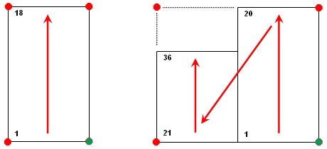
Column splitting is the ability of parts list columns to wrap when the number of data rows exceeds a configurable threshold value. The following image shows one parts list with 18 data rows and another with 36. Column splitting occurs when the number of rows exceeds the threshold value of 20. The insertion point appears as a green dot.

Instead of specifying the threshold value, you can define the number of sections to which the columns must split. In this case the data rows split evenly among the number of sections you define.
We recommend that you configure parts lists before you start drawing. Parts list follow the options you set. If you change the part list configuration settings after you create part lists, only text height settings apply to them. None of the other settings apply to existing parts lists.