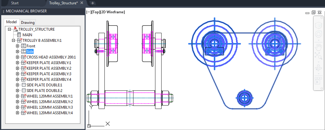
In a 2D environment, a part or assembly is typically shown by one or more views.
In essence, model space contains views of parts and assemblies (components). Grouping lines, arcs, and circles (geometry) as parts means that you select the geometry and group them as the views of part components. In the mechanical browser, the views of a part are collected below a part node and is indicated by the ![]() icon. The part node serves as a holding mechanism for views, and also contains BOM-related information for that part.
icon. The part node serves as a holding mechanism for views, and also contains BOM-related information for that part.
Example
 |
In this example, the assembly, TROLLEY, has two views that are shown in model space and the mechanical browser. The view that is selected in the mechanical browser is highlighted in model space.
Creating Components
When you choose to create a new component, you are actually creating the first view of a new component. Prior to prompting you to select geometry for the component view, AutoCAD Mechanical toolset prompts you for information about the component. It uses this information to update the BOM and create a component node on the mechanical browser.
You now have a component that has one component view. You must create component views for the remaining views of the part and pick the corresponding geometry from model space.
Once you finish creating a part component, you may find that you did not pick up all the required geometry for a component view. Similarly, you may also find that you accidentally picked up geometry that belong to another part. For both cases, the Edit objects right-click menu (AMSEDIT) on the mechanical browser provides options to add or remove geometry.