This finishing technique is best suited to machining areas that need a constant stepover and works well on near-horizontal faces.
Spiral toolpaths mill a feature in a series of offsets towards the feature center. The initial pattern is specified by taking the stock boundary, the feature boundary, or the curve specified on the Stock tab.
To use the stock boundary, click Use stock dimensions on the Stock tab. This results in an initial square shape to the toolpaths. The next and subsequent toolpaths are obtained by offsetting the initial shape in 3D (along the surfaces being cut). This differs from 2D spiral operations which offset the initial shape in 2D and then project this shape onto the surfaces.
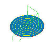
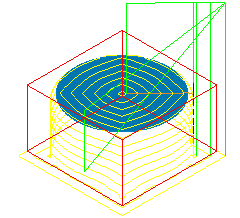
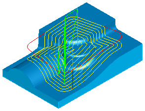
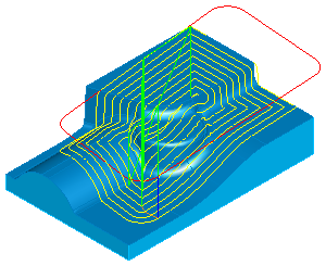
Select Use part surface Dimensions to use the silhouette of the part surfaces as the initial boundary shape as shown in the simple figure on the left. The figure on the right shows the toolpaths that would result if Use stock dimensions was used instead.
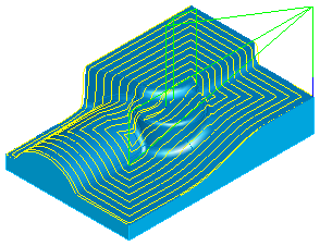
The Continuous spiral option in the Feature Properties dialog eliminates the stepover between the offsets, and morphs the pattern into a continuous spiral. With the Continuous spiral option selected, you get the result shown below. You can see that this minimizes the number of tool retracts and converts the original closed contours into one long spiral.
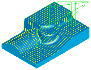
With the Continuous spiral option deselected, you get the following result. Notice that there is a retract between each contour.
You can also use boundary curves to control the shape of the spiral. All of these options are accessed by clicking the Curve options button on the Stock tab. By specifying a boundary curve, this shape is used as the initial contour of the spiral.
The boundary curve is clipped against part surfaces as shown in the figure below. If the curve is entirely outside of the stock, the silhouette of the surfaces is used as the boundary curve.
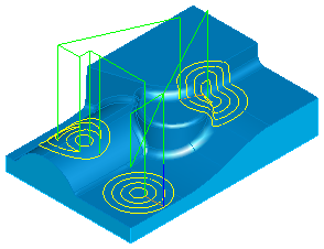
If the operation is specified as a boss, then boundary curves determine regions that are avoided.
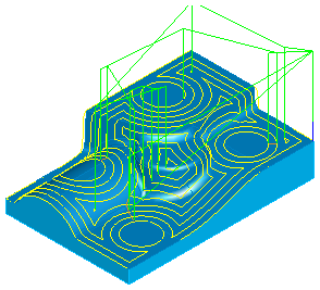
If the operation is specified as a pocket, then the boundary curves represent the shape of each region. Any island curves are avoided. In the example below, the operation is specified as a pocket with three boundary curves. The lower left region also has a circular island region.
Details of 3D spiral milling
- The Z height of any boundary curve is ignored. This means that the curve can be above, below, or even inside of the part.
- The Total offset option in the Boundary curve dialog is disabled for 3D spiral milling.
- Curve allowance is the same as described for 2D spiral milling.