Use the Stock tab of the Surface Milling Properties dialog to choose the clipping curves for the material to be removed.
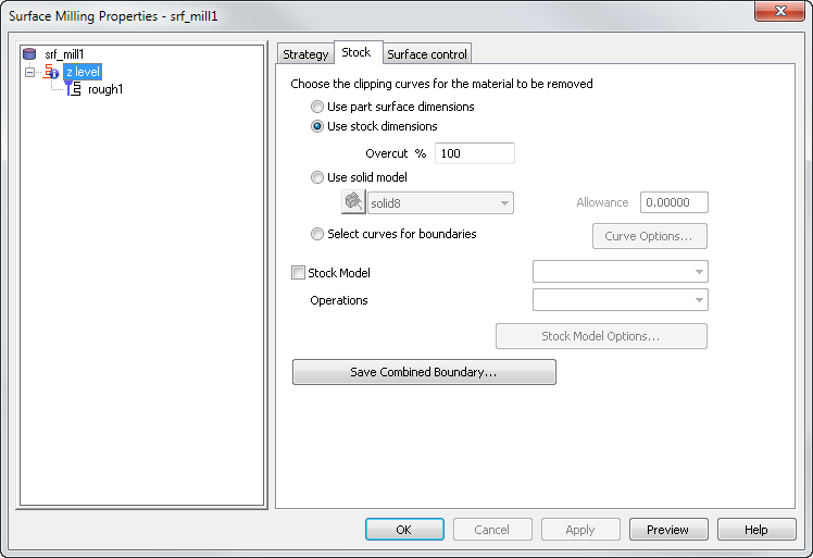
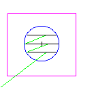
Use part surface dimensions — This creates toolpaths on the surfaces regardless of the location of the stock. If you are using a spiral toolpath, this option automatically calculates the silhouette curve of the feature and uses this curve as the shape of the spiral. This generally has the best shape for spiral toolpaths.
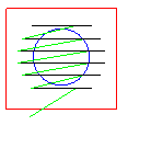
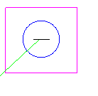
Use stock dimensions — This restricts the toolpaths to the portions of the surface feature that are within the stock. If you are using a spiral toolpath, this option uses the outline of the stock as the shape of the spiral. You can set what percentage of the tool approaches or passes beyond the stock boundary in the Overcut % option.
Overcut % applies to three types of surface milling features:
- spiral toolpaths designated as a boss on the stock page
- features cut with projection milling technique that do not have an explicit boundary curve
- some Z level rough passes.
In the boss case this attribute applies only to how the toolpaths behave around the stock boundary.
For other 3D surface milling features, use the cut allowance feature described on the Stock tab. The Overcut % option applies only if Use stock dimensions is selected on the feature's Stock tab.
Overcut % specifies what percentage of the tool approaches or passes beyond the stock boundary.
It can have a value between -100 and 100 with the following meanings:
0 puts the centerline of the tool on the stock curve.
100 overcuts the region by a tool radius.
-100 stops one tool radius short of the stock curve.
For Z level rough, this attribute applies to all features except Pocket features without stock curves. This attribute controls the outer extend of Boss features and the amount that Pocket feature cuts beyond its boundary. The default value is 100% which puts the edge of the tool on the boundary. A number greater than 100 extends the toolpaths beyond the boundary. A number less than 100 essentially offsets the outer boundary and clips the toolpaths against this closer boundary.
Use solid model — This restricts toolpaths to be within the solid model or STL model that you choose. Optionally enter an Allowance.
Select curves for boundaries — This uses curves to restrict the toolpath boundaries or to affect the shape of a spiral toolpath. Click the Curve Options button to open the Boundary Curve dialog. Additional options are displayed for 2D spiral toolpaths, 3D spiral toolpaths, and all other techniques.
Stock Model — Select this check box to use a stock model in combination with the curve you selected. Select the Stock Model name and the Operations to use from the lists. Click the Stock Model Options button to open the Stock Model Settings dialog.
Save Combined Boundary — Click this button to display and save the boundary for the operation. The boundary is a combination of the edge boundary, the stock curve boundary, and the slope limit. This may take some time to compute, but is computed and stored with the operation, that is, computed only once.