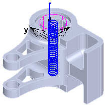
You can use the Toolpaths tab of the Milling Feature Properties dialog to edit a Toolpath feature.
When you select this tab, the Toolpath feature is shown in blue on the part, for example:
Data column
This shows the coordinates of the move. The coordinates have one of these icons on the left side.
 rapid move
 linear move
 arc move
 G-code, single line
 G-code, multiple line
Feed column
This shows the feed rate. If it is listed as a rapid move, this column displays Rapid.
Comp column
This lists the cutter compensation state for this move. It can be left, right, off, or blank. If the entry is blank, then this move does not change the cutter compensation status.
Coolant column
This records the coolant setting for each move. To change the coolant setting, right-click a row and select Set coolant to display the Set coolant dialog.
The toolpath is displayed as a series of points. If you select a row in the table, the move is shown in red in the graphics area.
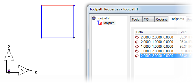
To locate a particular point, or series of points in the table, drag-select the points in the graphics window and the appropriate rows of the table are highlighted.
Toolpath editing commands
 The
Edit segment button opens the
Edit Toolpath Segment dialog to enable editing.
The
Edit segment button opens the
Edit Toolpath Segment dialog to enable editing.
 The
Delete segment button opens the
Delete Toolpath Segment dialog.
The
Delete segment button opens the
Delete Toolpath Segment dialog.
 The
Split segment button opens the
Split Toolpath Segment dialog.
The
Split segment button opens the
Split Toolpath Segment dialog.
 The
Add curve button opens the
Add Toolpath Curve dialog.
The
Add curve button opens the
Add Toolpath Curve dialog.
 The
Add segment button opens the
Add Toolpath Segment dialog.
The
Add segment button opens the
Add Toolpath Segment dialog.
 The
Add NC code text button opens the
Add NC Code Text dialog.
The
Add NC code text button opens the
Add NC Code Text dialog.
 The
Export toolpath as curve button opens the
Extract Toolpath Curve dialog.
The
Export toolpath as curve button opens the
Extract Toolpath Curve dialog.
 The
Add operation button opens the
Add Operation to Toolpath dialog.
The
Add operation button opens the
Add Operation to Toolpath dialog.
 The
Options button opens a
context menu.
The
Options button opens a
context menu.