Appearances more accurately represent the material you use on a part.
Appearances are listed by type, and each type has unique properties. Appearance definitions include properties such as color, reflectivity, transparency, self illumination, patterns, texture images, and bump maps. The properties combine to provide a unique appearance. Appearances that are assigned to a material are one of the assets of a material definition. You can use appearance assets to override the appearance assigned to a material. For instance, if a material in steel looks like metal, override the appearance with a finish appearance, such as chrome plating, anodizing, or paint.
The Autodesk Appearances Library, installed with a product or suite, provides an assortment of Appearance assets. Products such as AutoCAD, Inventor, and Revit share this read-only library to ensure a more consistent viewing experience across products.
Appearances are divided into categories, such as Metal, Plastic, and Ceramic. Categories contain various types of related appearances. For example, the category Metal contains types such as Aluminum, and Steel. Each material type has unique specific appearance properties.
Appearance Display Priority
- Face appearance
- Feature appearance
- Body appearance
- Part appearance
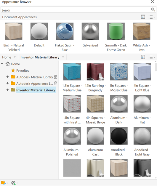
Appearance Browser
The Appearance Browser provides access to create and modify the appearance assets within the document, and to access the appearances located in the available libraries.
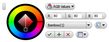
- Appearance Defines the appearance asset with various properties. The properties are unique to each appearance asset. You can edit the texture image or procedural maps assigned to the appearance asset.
- Color
- Image
- Image Fade
- Glossiness
- Highlights
- Reflectivity
- Transparency
- Index of Refraction
- Cutouts
- Self Illumination
- Bumps
- Tint
Adjustment of appearances
When you require a different textured appearance on a specific face, use Adjust Appearance and Texture Manipulator. You can modify the appearance of a component, feature, or face. The two devices provide different levels of appearance asset interaction.
With Adjust Appearance, you can modify the appearance assignment, color, and texture mapping.
Texture Manipulator
The Texture Manipulator provides in-canvas tools to move, scale, or rotate the appearance texture on any face. While using Adjust Appearance, when you select a textured appearance, the Text Manipulator displays.
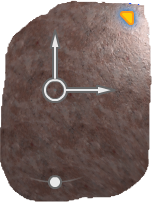
Images as maps
The images assigned to materials are called maps. Maps improve the material appearance and add realism by simulating surface texture and other effects. Maps used with materials add details without adding complexity to model geometry. When you assign an appearance having an image map to a material, the map color replaces the material diffuse color. For transparency, the map texture is a multiplier.
You can scale, tile, or rotate maps. You can use a map for multiple purposes. Thus, they are nested in the material. You can create high end custom materials.
Appearances utilize two types of maps: image and procedural.
Texture image and material color combinations
When applying a texture to a part, you can determine to what degree the texture color influences the part. With the Appearance Editor, you specify the Image Fade value. The Image Fade value is an opacity setting for the texture image. For example, combining a beige colored texture with an Image Fade value of 50 with a blue material color, results in an equal blend of the two colors.
If you want the texture to display on the part with exact fidelity to the texture color, set the Image Fade value to 100.
Custom texture maps
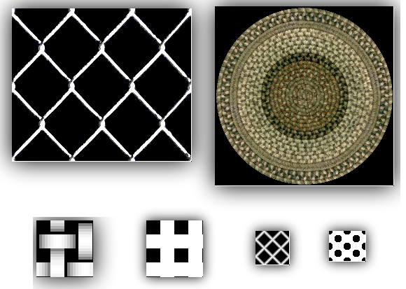
You can define, store, and apply your own textures in a custom library. For example, you can define a texture to represent a series of holes, or slots in a part such as a grill or a screen. There is no need to model each hole or slot for manufacturing or analysis. For convenience and economy, you can represent each hole or slot as a texture rather than a modeled feature. You can create textures with transparent pixels so that a part displays as transparent wherever the transparent pixels exist.
Defining your own textures gives you the flexibility to customize the texture color, pattern, and size precisely. You can use image-editing software to adjust the texture map pixel measurement and dpi resolution. With this method, you can create texture patterns that match the scale of the target parts.
Procedural maps
A fixed matrix of colored pixels product a bitmap image , while a mathematical algorithm generates a procedural map. Consequently, the types of controls for a procedural map vary, depending on the capabilities of the procedure. You can generate a procedural map in either two or three dimensions. You can nest a procedural map within another procedural map to add depth and complexity to the material.
Procedural maps are used with appearance texture and cutout maps. You can access them from color or image edit points.

Cutout Maps
Using Appearances in assemblies
It can be useful to display an assembly component in an appearance other than the material appearance. For example, all components purchased from a single vendor or designed by a particular designer can be displayed with one appearance. Displaying an entire subassembly in one appearance (instead of the unique material appearances) can simplify the display. Using a transparent appearance (such as the predefined "glass") can be useful if a component obscures others behind it.
Appearance assignments are saved in design view representations allowing you to strategically use appearances to manage your model views. Changing component appearances at the assembly level affects only that component occurrence.