Flow Geometry
Geometry for a typical fluid flow analysis is different than that used for structural analysis. The two broad classifications of flow geometry are internal and external.
Examples of internal flows include:
- Flow in pipes
- Flow in valves
- Flow in electronic enclosures
Examples of external flows include:
- Flow over a car
- Flow over an airplane wing or missile
- Flow around an electronic device exposed to the environment
Internal Flows
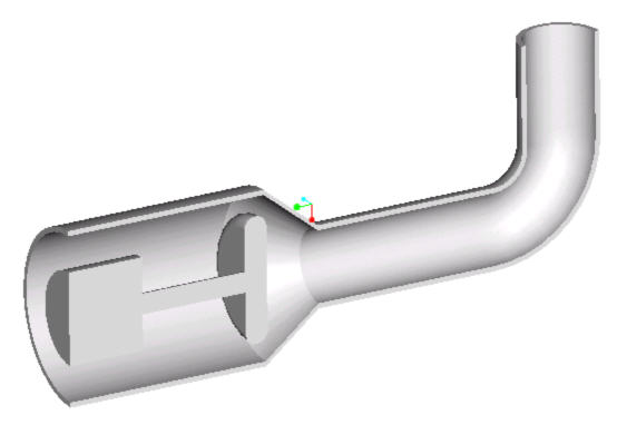
For internal flows, a flow core must be created from the existing surrounding geometry. The outer walls of the volume are omitted (unless they are to be used as part of a heat transfer calculation) and the interior volume of the pipe is modeled.
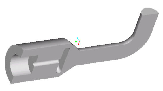
In contrast, in a structural analysis the walls of the pipe would be meshed and the interior would be omitted from the calculation domain:
Another way to think of this is:
A pipe is filled with water and the water is allowed to freeze. Now, imagine that the pipe walls are removed, and all that remained was the solid volume of ice. This volume is where the fluid exists, and is the geometry that would be created and meshed for a CFD analysis of flow through that pipe.
The flow volume can be created directly in the CAD tool (Pro/Engineer, Inventor, CoCreate, Solid Edge, SpaceClaim, UGNX, SolidWorks) or with the Autodesk® CFD Void Fill Geometry Tool. An additional technique is to create a volume in the CAD model that covers each opening. Autodesk® CFD automatically creates parts to fill fully-bounded, air-tight voids.
Example showing an internal flow volume
External Flows
For external flows, it is customary to "invert" the geometry. This means that the object is made stationary and the flow is blown over it at the equal and opposite velocity of the physical object. To implement this as analysis geometry, two pieces of geometry are needed: the object itself (missile, car, bullet, etc.) and a large calculation domain in which the object is positioned:
The flow volume can be modeled directly in the CAD tool (Pro/Engineer, Inventor, CoCreate, Solid Edge, SpaceClaim, UGNX, SolidWorks) or with the Autodesk® CFD External Volume Geometry Tool.
The shape of the domain is usually not very critical, and can be a circle, semi-circle, rectangle, sphere, or box. Because the flow all around the object is being modeled, it is a good idea to make the computational domain substantially larger than the object itself.