The Physical Material has Standard and Advanced parameters to encourage the best-practice use of avoiding non-physical adjustments, while not making them impossible.
The user interface for the Physical Material has two modes: Standard and Advanced. Advanced mode is a superset of Standard mode, including hidden parameters. The Physical Material has Standard and Advanced parameters to encourage the best-practice use of avoiding non-physical adjustments, while not making them impossible. In most cases, the parameters in the Standard mode are sufficient to make most physically plausible materials.
Advanced parameters include:
- Reflection Color and Weight. In the real world, the surface of a dielectric material does not really vary in reflectivity very much, but it does vary a lot in how it scatters light. Since changing the roughness of a material varies the perceived intensity, this is where variations should generally go. Traditionally, people have used intensity maps for reflections; but in physics, everything (generally) reflects. It's just a matter of how much it scatters those reflections around. These parameters are hidden to encourage roughness variations rather than reflective intensity variations.
- Diffuse Roughness is from the Oren/Nayar diffuse model. While useful, it is somewhat physically questionable. It exists only in Advanced mode mostly for similarity with legacy materials such as Arch & Design.
- Advanced Reflectance Parameters rollout and the manual reflectivity curve are hidden because they are physically dubious. In the real world, reflections are guided by the Fresnel reflectivity of the given dielectrics IOR. When stronger reflections occur, they are either from a material with a different IOR (Index of Refraction) or caused by a mixing in of metals. In the Physical Material these can be simulated by adding a degree of Metalness instead. The manual curve exists in Advanced mode for greater control and compatibility with legacy materials like Arch & Design; it should be used sparingly to remain true to physics.
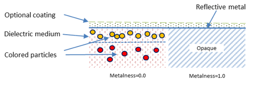
The Metalness interpolates between two basic underlying shading models:
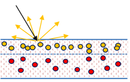
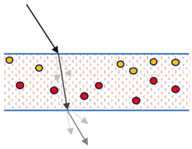
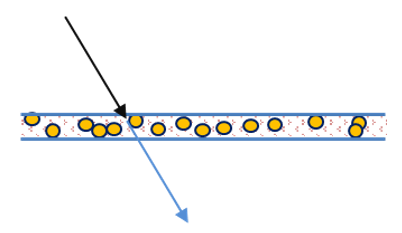
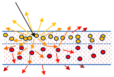
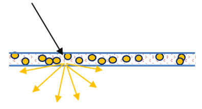
- When Metalness is 0.0, the physical model of the material is that of a dielectric carrier material with suspended colored particles within. The density and color of these particles define the diffuse color, the absorption in the material, and the scattering. The light enters the dielectric, interacts with the particles, and reflect or refract back out of it.
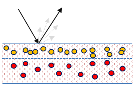
- When Metalness is 1.0, the physical model of the material is that of a solid metal object. Light reflects off the surface of the object, being colored and scattered only by the surface. No light enters into the object, making it opaque.
On top of this base material is an optional coating layer.
Base Color and Reflection
Base Color and Reflection are the reflection off the surface as well as diffuse reflections, which are reflections in the very top layer of colored particles inside the material.
Reflections
Base Color/Diffuse
- When Metalness is 0.0, the base weight and color defines the material's diffuse reflectance. The reflective layer that has the reflection weight and color (only shown in Advanced parameter mode) with the weight multiplied by the angular function.
- When Metalness is 1.0, the base weight and color defines the reflectance of the metallic reflections. The angular function interpolates between that color (for reflections facing the viewer) and the reflection color (for reflections on the edges).
Note: Metals are always reflective and the reflection weight is ignored.
The roughness of the reflections are defined by the reflective roughness parameters; where 0.0 is a completely smooth and mirror-like surface, and 1.0 is an extremely rough, diffuse looking surface. You can invert the interpretation, causing 0.0 to instead be interpreted as extremely rough, and 1.0 to be mirror smooth. This is to facilitate the re-use of existing traditional shininess or glossiness maps, which have the opposite interpretation.
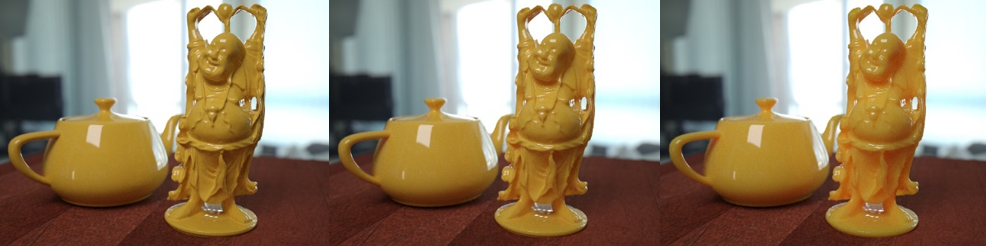
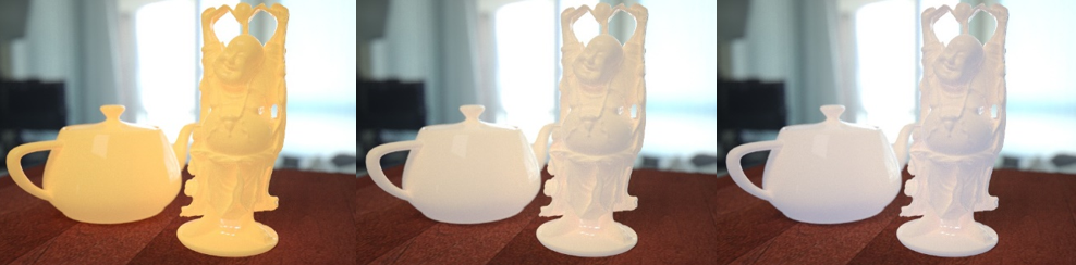
When Metalness is 0.0, you see a colored base layer with a generally white reflection on top. Note how the reflective intensity is perceived to be weaker as roughness goes up, because light energy is spread wider.
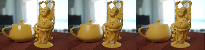
Metalness=0.0 and Roughness=0.0, 0.3 and 0.6 respectively
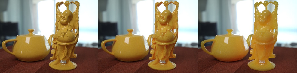
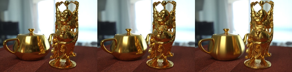
When Metalness is 1.0, you do not see the base layer, just the colored reflection. The reflection color comes from the base color and base weight, except on edges where it comes from the reflection color (generally white).
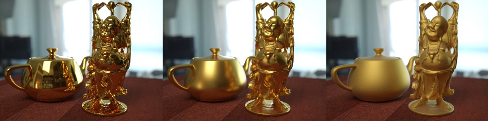
Metalness=1.0 and Roughness=0.0, 0.3, and 0.6 respectively
The IOR parameter (Index of Refraction) defines the material's Fresnel reflectivity, and is by default the angular function used. The alternative is a curve you manually define in the Advanced parameters. Effectively the IOR will define the balance between reflections on surfaces facing the viewer and on surface edges. You can see the reflection intensity on the teapot's lid remains unchanged but the reflection intensity on the front side of the teapot changes a lot.
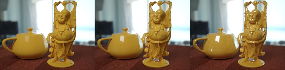
IOR=1.2, 1.5 and 2.0 respectively
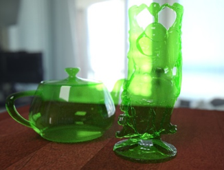
Transparency
The transparency sets how opaque or see-through the object appears. Light will be refracted and can be colored by the surface or potentially be absorbed in the material.
Transparency
The Roughness defines the transparency's clarity, where 0.0 is clear like window glass and higher values appear like frosted glass. By default, the transparency roughness value locked as the same as the reflectivity roughness. You can unlink the values by deselecting the lock icon.
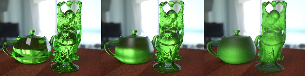
Roughness=0.0, 0.3 and 0.6 respectively
The Depth parameter enables absorption into the material. If the depth is 0.0, a traditional computer graphics model of transparency is used, where light becomes colored at the surface and is not effected by travelling inside the medium. Therefore the object's thickness has no affect.
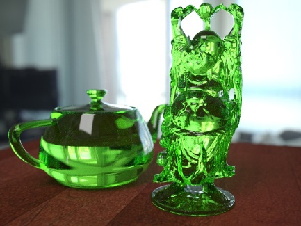
Depth=0.0
However, if the depth is not 0.0, the light will be effected by absorption in the medium in such a way that at the designated depth light will have the given color.
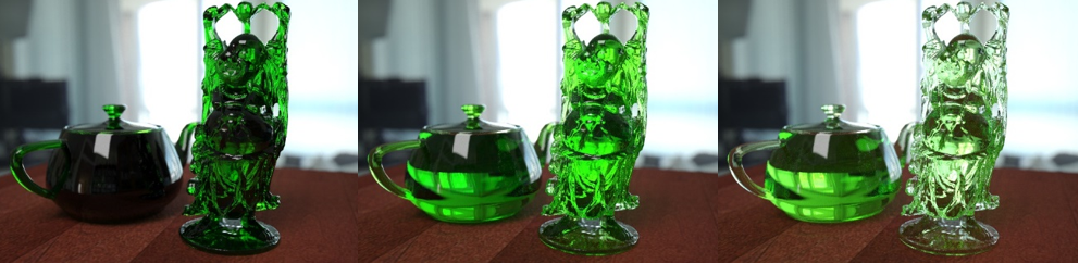
Depth=0.1cm, 1.0cm and 5.0cm respectively
Thin-walled Transparency
The Thin-walled parameter makes objects appear as if they are made of a thin shell of material, rather than being solid. This can be used when modelling windows by a single face.
Thin-walled=on
Sub-surface Scattering and Translucency
This parameter models scattering of light inside the object. Unlike transparency, which makes the object see-through, sub-surface scattering is about transporting light within the material without actually being able to see through it in any meaningful way. Light is bounced around and different wavelengths are absorbed differently, allowing the light to become colored the further it travels in the material.
Sub-surface Scattering
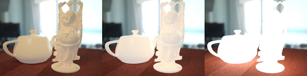
The Sub-Surface Scattering (SSS) parameter shares its energy with diffuse shading, so increasing its weight fades from normal diffuse shading to shading with SSS. The SSS Color is the color at the surface, essentially the colorization of the entire SSS effect.
SSS Weight=0.0, 0.5 and 1.0 respectively
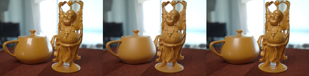
The Depth parameter defines how deeply light penetrates into the object. Scale is a pure linear scale to depth that can be texture-mapped, allowing the scale to change across the object. When the depth is 0.0, the shading is effectively identical to pure diffuse shading. The higher the depth, the more light penetrates the object.
SSS Depth=0.0, 0.1 and 1.0 respectively
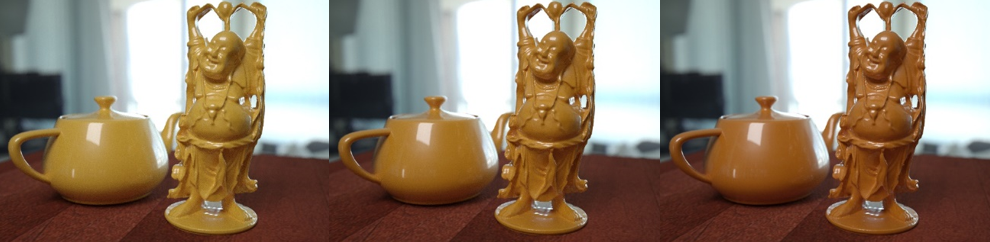
The Scatter Color parameter defines how light gets tinted as it travels inside the medium. Technically, the depth multiplied by the scale is the mean free path of scattering within the medium and the scatter color is an additional scale factor for the red, green and blue paths.
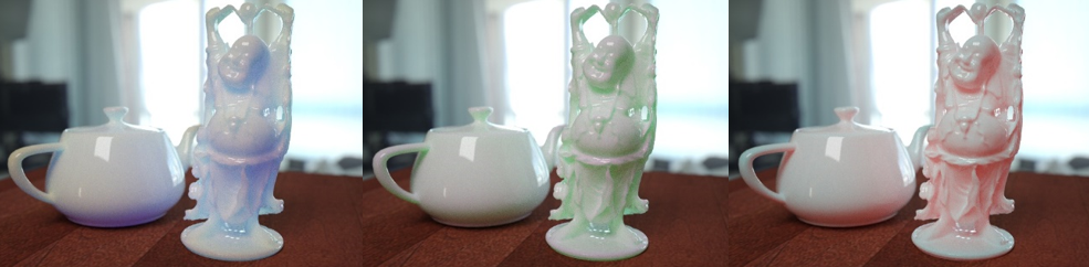
White surface color with Scatter Color=blue, green and red respectively
Generally, red light scatters further than green, which scatters further than blue. For this reason, the default Scatter Color of 1.0, 0.5 and 0.25 is a reasonable starting point.
When Thin-Walled mode is enabled, it becomes classic translucency. This is because SSS is a volumetric effect and Thin-Walled mode has no volume.
Thin-walled Translucency
The appearance of this effect is like a thin sheet of paper letting some light through to the back side. In the following example, this effect is illustrated by placing a square in the scene and modifying the light direction.
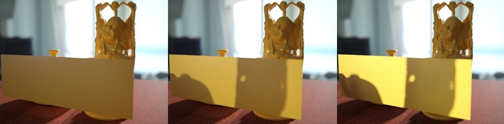
Translucency=0.0, 0.25 and 1.0 respectively
Emission
The Physical Material supports an emissive component, additive light on top of other shading. Emission identity is defined by the weight and color multiplied by the luminence, and also tinted by the Kelvin color temperature (where 6500=white).
Luminance=1500, 5000 and 50000 respectively
Kelvin color temperature=3000, 6500 and 10000 respectively
Anisotropy
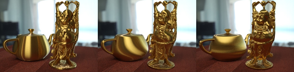
Anisotropy is an effect seen in materials such as brushed metal, where a particular grain direction gives the visual effect of having a different surface roughness in different directions. Highlights and reflections appear "stretched" in a particular direction.
The Anisotropy parameter defines how "stretchy" the effect is. In principle, it is the ratio between the horizontal and vertical roughness values. This means a value of 1.0 is not stretched.
Anisotropy=1.0, 0.5 and 0.1 respectively
The anisotropy effect can be rotated using the Rotation parameter, where 0.0 to 1.0 is a full 360 degree rotation.
Rotation=0.0, 0.12 and 0.25 respectively
Advanced Reflectance
- Facing - the reflectance on faces in the viewer direction
- Edge - the reflectance from gazing view angles, on edges
- Slope - the curve's shape between two endpoints.
Coating
The Physical Material has a feature to coat the material. It acts as a clear-coat layer on top of all other shading effects. The coating is always reflective (with the given roughness) and is assumed to be dielectric. Reflectivity is based on the Fresnel equation from the given Coating IOR, and reflections are always white.
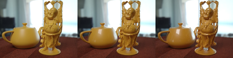
Coating Weight=0.0, 0.5 and 1.0 respectively
The coating layer can also have differing roughness values.
Coating Roughness=0.0, 0.25 and 0.5 respectively
In the real world, when a material is coated there is a certain amount of internal reflections on the inside of the coating. This causes light to bounce onto the surface multiple times before escaping, allowing the material's color to have an enhanced effect. An example of this is varnished wood. This effect can be achieved using the Affect Underlying Color parameter.
Affect Underlying Color=0.0, 0.5 and 1.0 respectively
The coating itself can also have a color. This is the color of the coating layer's transparency. In the following example, a diamond shaped map has been applied to the Coating Weight and different Coating Colors used.
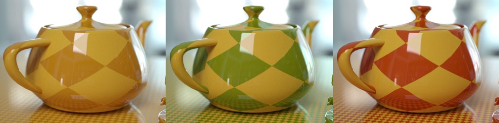
Coating Color=white, green and red respectively
In the example on the left, the coating is only changed by the darkening effect of the Affect Underlying Color parameter, whereas the examples on the right are further affected because they are being seen through the coating color itself. This is similar to painting the object in a semi-transparent layer of paint or laquer.
The coating also has an Affect Underlying Roughness parameter. This causes the coating's roughness to have an effect on the underlying layer's roughness, simulating the blurring effect of being seen through the top layer.
In the following example, a red tinted coating has been used on top of a base color with Metalness set to 1.0.
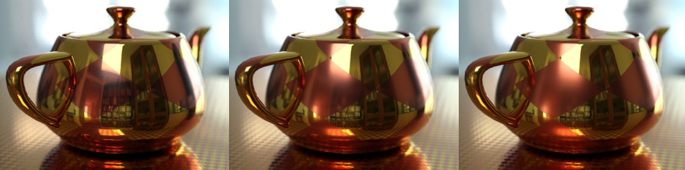
Affect Roughness=0.0, 0.5 and 1.0 respectively
In the example on the left, the metal covered by the red coating is unaffected, whereas the examples on the right yield a blurred appearance.
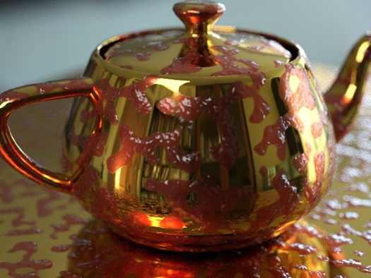
The Coating parameter also has a separate bump map. This allows you to generate some interesting effects using the coating layer, such as a brass teapot covered in jam.