To Place Assets in Inventor
General workflows for placing assets onto your layout and move a placed asset from one layer to another.
To place assets in your Inventor layout
The following provides a general workflow for locating and placing content from the Factory Assets library into a factory layout assembly.
- On the Factory tab, click Palettes
 and select Asset Browser.
 - Search for assets in the Asset Browser using the Search option, or manually navigate to components in the library directories.
- If you're using layers, set current the layer on which to place the asset.
- Using the appropriate snap type from the Snap Types drop-down menu, place the asset in the factory layout assembly.
- To automatically place and ground the asset at the layout origin (0, 0, 0), right-click when placing the asset and select Insert Grounded at Origin.
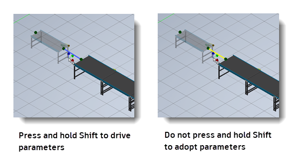
- When placing an asset or reconnect a previously placed asset into your layout, press and hold down Shift and pass the parameters of the asset you're placing into the existing assets you're connecting the asset to. For more information, see To Adopt or Drive Parameters When Placing Assets.
- Click on the asset in the layout and modify the Layer, Model, or User Defined parameter values of the asset, if required.
- Continue to locate and place additional assets, as necessary.
- Use the Reposition command in the Utilities panel on the Factory ribbon to make minor adjustments to an asset's XYZ placement or angle.
To place a group of assets into your layout
The Insert asset group ![]() command lets you copy a group of asset instances from within any Factory layout file and then reuse it in your current layout.
command lets you copy a group of asset instances from within any Factory layout file and then reuse it in your current layout.
- In the Asset Browser tool panel, select the Insert asset group
 command.

- In the Insert Asset Group dialog box, select the source layout file containing the group of asset instances you would like to place into your layout.
- Click anywhere in your layout to place the group of assets. Only the asset instances and their relative positions are copied and the new asset instances are no longer associated with the group of assets in your original factory layout.
To place asset library components (with published landing surfaces) in factory layout assemblies
System Assets and User Assets content are placed in the factory layout assembly directly from the Asset Browser.
- Locate the asset in the Factory Assets library.
- If you are using layers, set current the layer on which you wish the asset to place the asset.
- If the component is an asset variant, right-click and select the desired variant from the Asset Variant submenu.
- Press and hold the left mouse button and drag the asset into the factory layout assembly.
- If multiple insertion points have been defined on the model, press the Tab key to cycle through each of the insertion points until you identify the point you want. To automatically place and ground the asset at the layout origin (0, 0, 0), right-click when placing the asset and select Insert Grounded at Origin.
- Release the mouse button.
Method 1 - Place independent assets
- Drag the asset to the required location in the assembly and select once using the left mouse button.
- If multiple insertion points have been defined on the model, press the Tab key to cycle through each of the insertion points until you identify the point you want. To automatically place and ground the asset at the layout origin (0, 0, 0), right-click when placing the asset and select Insert Grounded at Origin.
- Continue to move the mouse to rotate the asset, or enter an angle in the value input box. Select again using the left mouse button to define the orientation.
Method 2 - Place assets using connectors
Assets that are published with connectors assigned can be used to help locate assets relative to the connectors on other assets.
- Drag the asset so that one of its connectors is within the specified Snap Preview Distance of a connector on the second asset being referenced. The connector points are indicated by green spheres. Once the asset is within the specified Snap Preview Distance, a yellow connector appears indicating a connection can be made.
- Continue to drag closer to the existing asset, and once you are within the specified Snap Distance the new asset is snapped into position. Press the left mouse button to confirm placement.
- In the rare event that a connection cannot be made, the connector points change from yellow to red spheres. This can occur if an assembly constraint was created that interferes with the connectors snapping together.
Method 3 - Place assets on grids
Published assets with a predefined landing surface contain a landing surface origin. The landing surface origin is used to locate the asset when it is snapped to the grid.
- Drag the asset to the intersection of two grid lines on the factory floor and select once using the left mouse button.
- If multiple insertion points have been defined on the model, press the Tab key to cycle through each of the insertion points until you identify the point you want. To automatically place and ground the asset at the layout origin (0, 0, 0), right-click when placing the asset and select Insert Grounded at Origin.
- Continue to move the mouse to rotate the asset, or enter an angle in the value input box. Select again using the left mouse button to define the orientation.
Method 4 - Place assets on layout sketches
Published assets with a predefined landing surface contain a landing surface origin. The landing surface origin is used to locate the asset when it is snapped to the sketch.
- Drag the asset to a sketch entity on the layout and select once using the left mouse button. Assets can be snapped to endpoints, midpoints, and along an entity.
- If multiple insertion points have been defined on the model, press the Tab key to cycle through each of the insertion points until you identify the point you want. To automatically place and ground the asset at the layout origin (0, 0, 0), right-click when placing the asset and select Insert Grounded at Origin.
- Continue to move the mouse to rotate the asset, or enter an angle in the value input box. Select again using the left mouse button to define the orientation.
Method 5 - Place assets on DWG underlays
Published assets with a predefined landing surface contain a landing surface origin. The landing surface origin is used to locate the asset when it is snapped to a selected location on a DWG underlay.
- Drag the asset to a 2D drawing entity on the DWG underlay and select once using the left mouse button. Assets can be snapped to endpoints, midpoints, and along an entity.
- If multiple insertion points have been defined on the model, press the Tab key to cycle through each of the insertion points until you identify the point you want. To automatically place and ground the asset at the layout origin (0, 0, 0), right-click when placing the asset and select Insert Grounded at Origin.
- Continue to move the mouse to rotate the asset, or enter an angle in the value input box. Select again using the left mouse button to define the orientation.
Continue to place additional instances of the same asset or right-click and select OK from the pop-up context menu to cancel additional asset placement.
Return to the Factory Assets library to locate and place additional assets, as necessary.
You can modify the location and orientation of assets after they are placed by using the commands on the Utilities panel on the Factory tab.
To place asset library components (without published landing surfaces) in factory layout assemblies
User Assets without a defined landing surface are positioned on the factory floor in the same way as unpublished models. For more information, see the Inventor Factory Help topic: Insert models.
For User Assets content without a defined landing surface, the component displays inside a bounding box. The sides of the bounding box are parallel to the component origin planes. The insertion point is the corner of the bounding box that aligns with the origin coordinate system.
To move a placed asset from one layer to another
- Select one or more assets from the factory floor layout. Press and hold the Ctrl or Shift keys for multiple selections.
- The layer name of the selected asset appears near the top of the Factory Properties browser. If multiple assets on different layers are selected, the layer name appears as *VARIES*.
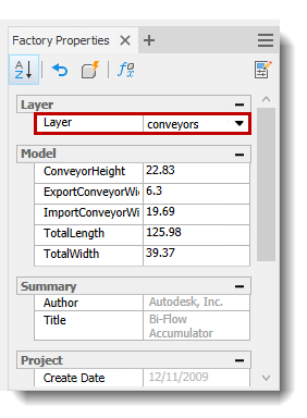
- Click the down arrow to the right of the layer name to display a drop-down list containing the names of all layers defined in the current layout.
- Select the layer you wish to move the selected asset(s) to.
- The drop-down list closes and the layer you selected replaces the previous layer name.
- Click the Update button
 in the Factory Properties browser toolbar to move the asset(s) to the different layer.
 - Press Esc, or click an empty area inside the graphics window, to turn off the selection highlighting.
See the topics listed in the links below to learn more about working with your assets in Inventor.