Spring calculation is performed in accordance with DIN or ANSI standards.
You can select standard sizes of springs from the DIN/Gutekunst/SPEC catalog. For simplicity, all spring types are inserted using the same method. To insert springs you use spring commands that take you through dialog boxes which let you select options for calculating and inserting springs.
When you select the Modified Design option, you can select the wire diameter from a table and define all other parameters separately. When you select the Only Draw option, you determine only the geometry of the spring without calculations. You can also insert an empty form into the drawing, and then insert values in it by double-clicking it.
The calculation procedure used depends on the standard and the selected spring type. For example, if you select the ANSI standard, you can select the catalog and the semi-finished products.
You can also determine whether you want to perform a calculation of the spring (buckling, transverse compliance, shock stress), which stress types are effective, or whether a selection of the spring list is to be made, as well as the sorting of the springs when dragging dynamically.
You can select a spring using one of two methods:
- From the Results dialog box, which lists all the springs found along with the calculated results (such as tension ratio, natural frequency).
- In the graphic area using dynamic dragging, where springs are displayed on the screen with the geometric dimensions. If only one spring is found, this dynamic dragging is not activated
Outline representation when dragging dynamically

For the outline representation, the routine takes the values from the database, and the corresponding spring is displayed on the screen with the geometric dimensions.
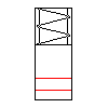
When you are in the process of dragging dynamically, the outline of the spring is represented such that you can see the unloaded length and the loaded length considering F1, F2, and Fn (in case of torsion springs, this is the fixed leg and the loaded length of the moved leg considering F2, F1, and Fn).
The representation is also dependent upon the selected specification method. The red line represents the spring length or force in the current situation, the outline the value L0 (unloaded length), the length provided with a helix the value Ln (maximum allowable length). If you move the pointing device away from the insertion point, a larger spring is shown; if you move it back again, the next smaller spring is shown. If only one suitable spring for the defined parameters is found in the database, no changes in size are made visible by dragging the cursor. The criterion for leafing is determined by the dynamic dragging option in the Additional Settings dialog box.
- If the thrust tension ratio has a calculated value that is greater than 1 (>1), a warning appears on the screen. You can either accept the calculated spring or choose the Previous and define new values.
- If the displayed spring outline fulfills your requirements, press Enter, or click a point on the screen. The Drawing dialog box for the spring representation opens.
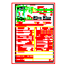
Empty form for springs

By selecting the Empty form option, you can insert a standard scheme in ANSI, ISO or DIN into the drawing.
You can select a form and determine the insertion point for the form in the drawing. To enter values in the form, double-click it.