 |
 |
- Click
 Feature Control Frame . Find
 - Select an object to attach the feature control frame to.
- At the command prompt, enter F. Note:
The surface option is available only if the revision of the standard in use permits surface indication lines
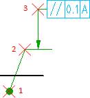
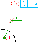
- Specify the start point of the surface indication line. (1 in the illustration above).
- Specify one or more points to define the vertices of the leader (2 and 3 in the illustration above), and then press ENTER.
- In the Feature Control Frame dialog box, enter the data.
- Click OK.