In the model used in this tutorial there is one outfall, 45631203, which currently has no level time series applied to it.
It is possible to apply a level time series supplied by telemetry to this location in a similar way to the way the rain gauges have been set up:
- Open the Scalar TSDB object by dragging it onto the main window or by right-clicking it and selecting Open. If using the provided database objects, use the Scalar TSDB - step 3 completed object.
- Select the
Observed tab:
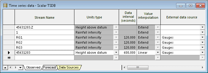
- Add a new stream:
- Call it 45631203.
- Set the Data interval to 600s.
- Set the Units type to Height above datum.
- Select the external data source to match that entered in the Data Source tab in Step 3 (Gauges).
- Ensure that the external units are set to
m AD.
- Right-click on the row for stream 45631203, and select Test connection.
- If the connection is OK then right click on the row again and select Update data.
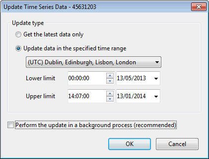
- The Update Time Series Data dialog is displayed.
- Enable Update data in the specified range and set the Lower limit to 00:00:00 on 13/05/2013.
- Disable the
Perform the update in a background process (recommended) option.
- Click
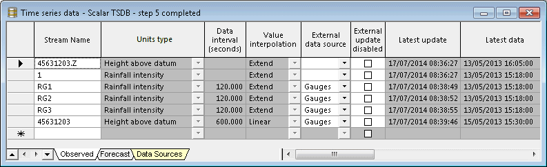
OK. Check that the
Latest updates and
Records values have been updated for the
45631203 data stream.
- Close the Scalar TSDB object.
- Add a new stream:
- Finally we must create a TVD Connector for the outfall, in order to allow the contents of the scalar TSDB to be applied to this location. Ensuring that the
Tutorial network - step 4 completed network is open in the GeoPlan Window:
- Add a GIS layer to the network on the GeoPlan (please click on this link for instructions on how to create a layer list).
- Drop the Scalar TSDB on top of it (so its name appears in the title bar of the GeoPlan window).
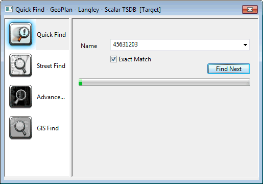
- Search for the outfall (45631203) using the
Find Objects
button (
 ) of the
GeoPlan Tools toolbar. Close the Quick Find dialog once the outfall has been found and is highlighted on the GeoPlan.
) of the
GeoPlan Tools toolbar. Close the Quick Find dialog once the outfall has been found and is highlighted on the GeoPlan.
- Zoom in very close to the outfall to ensure the TVD connector to be created will be digitised at the exact same location.
- Using the
Object Type dropdown set to
Point in conjunction with the
New Object button (
 ) of the
GeoPlan Tools toolbar:
) of the
GeoPlan Tools toolbar:
- Digitise a point object on top of the outfall 45631203.
- Make the point type
TVD connector and call it
45631203Live
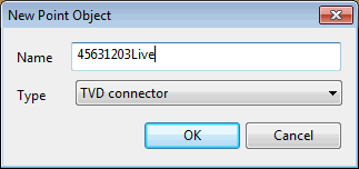
- Click on OK. The Object Properties window is opened with the properties of the newly created TVD connector.
- In the properties of the TVD Connector object:
- Specify all the input units types as Z and select #45631203 as Input A, indicating that it is connecting to external data source called 45631203.
- Ensure that the
Connected object type is set to
hw_node (Node) and that the outfall node ID (45631203) is specified as the
Connected object ID field.
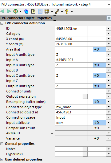
- Validate the network and commit the changes.
- Open the last simulation called Test TSDB - with rain gauges, Nowcast and Nimrod RADAR data.
- Give it a new name, for example, Test TSDB - with rain gauges, Nowcast, Nimrod RADAR data and boundary conditions at outfall.
- If using the provided data, please use the Tutorial network- step 5 completed network object and the Scalar TSDB - step 5 completed TSD objects.
- In the TSD Options dialog, update the time series data to use the latest and ensure that the run origin is set to 12:15, 14/05/2013 and that Historic mode is checked.
- Update the network to latest.
- Investigate the results at the outfalls. Note that as Historic mode has been used, the outfall level data will only be used up to the run origin.
Tip: It is possible that warning and information messages are reported in the
Output Window. Ensure that no errors (red icon) are found.
One function of any successful operational system is the ability to alert the operator that something of interest is happening or more accurately, has been predicted to happen, within the system. In ICMLive this is done by means of alerts. We are going to demonstrate now how to configure and use alerts. Please refer to the Setting Up Alerts topic.