 Back to
previous stage.
Back to
previous stage.
There are a number of methods available to build banks. Banks can be built from bank lines in a similar way to the river reach creation from cross sectional lines or they can be imported from an external source. However, the method used in this tutorial will be to manually draw a bank line and use the ground model to update its properties.
- Ensure that the River example network and the DTM ground model are both open on the GeoPlan. Alternatively, if you have not completed the previous steps, please use the provided River example - step 2 completed network as a starting point.
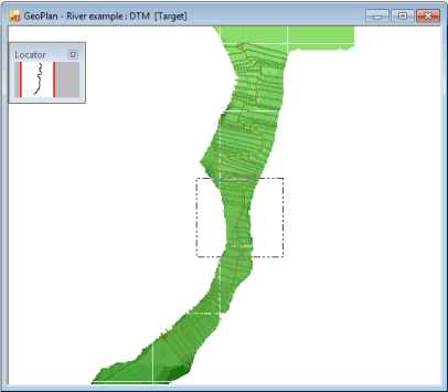
- Zoom in to the area of the river reach shown below. For your information, the area of interest is located between cross section lines XS377 and XS388. You may use the Find functionality available in InfoWorks ICM via the Find in GeoPlan button of the GeoPlan Tools toolbar. Please refer to the Finding Objects on the GeoPlan topic of the Help for further details.
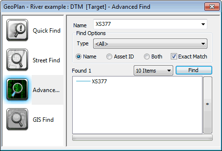
- If making use of the functionality mentioned above, the screenshot of the GeoPlan Find dialog shown below should help you locate cross section line XS377 on the GeoPlan:
- Select
Line in the
New Object Type box and click on the
New Object button (
 ) of the
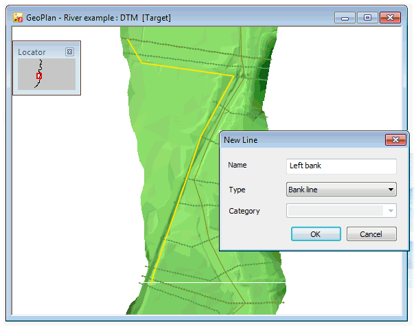
GeoPlan Tools toolbar and draw a bank line through each cross section in this area of river reach as shown below. The line illustrated in the screenshot below goes from cross section line XS378 to cross section line XS387.
) of the
GeoPlan Tools toolbar and draw a bank line through each cross section in this area of river reach as shown below. The line illustrated in the screenshot below goes from cross section line XS378 to cross section line XS387.
- At the end, double-click to finish.
- The New Line dialog is displayed. Enter an appropriate name for the line (Left bank, for example).
- Select Bank line in the Type dropdown list. Click on OK.
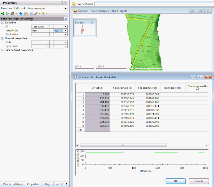
- This bank line currently has no elevation, discharge coefficient or modular limit values. Using the
Properties button (
 ) on the
GeoPlan Tools toolbar, click on the line to display its property sheet. Click on the
) on the
GeoPlan Tools toolbar, click on the line to display its property sheet. Click on the
 button adjacent to the
Bank data section.
button adjacent to the
Bank data section.
- Once you have finished looking at the data, click on OK to close the Bank Data dialog.
- The next step is to take the elevations from the ground model.
- Select the bank line in the GeoPlan with the help of the
Selection tool (
 ) and use the
Update from ground model... option from the
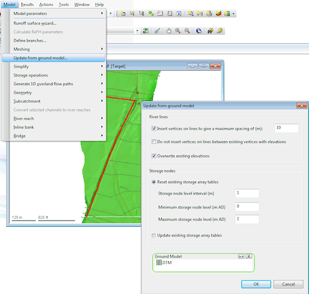
Model menu to automatically read the elevations data from the LiDAR data. Tick the
Insert vertices... check box to give max spacing of 10m and ensure the
Overwrite existing elevations check box is also ticked.
) and use the
Update from ground model... option from the
Model menu to automatically read the elevations data from the LiDAR data. Tick the
Insert vertices... check box to give max spacing of 10m and ensure the
Overwrite existing elevations check box is also ticked.
- Click on OK on the Update from Ground Model dialog.
- Re-open the Bank data dialog via the bank line property sheet. You will see that the bank levels have been updated by sampling the currently loaded Ground Model. However, the discharge coefficient and modular limit values are still missing.
- Click on OK to close the dialog.
- We need to add a discharge coefficient of 1.0 and a modular limit of 0.9 for each point along the bank line. This can be done by manually inserting the desired values in the
Bank data dialog or using an
SQL query.
- If you want to manually add the values:
- Open the Bank line property sheet.
- Click on the
button adjacent to the
Bank data cell.
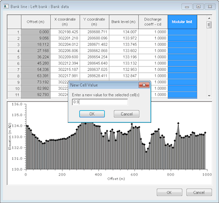
- Click on the header of the Discharge Coeff - cd column. This selects the whole column.
- Right-hand click in any of the selected empty cells (not the header) and select Set new value(s) for cell(s).
- Enter 1 in the New Value dialog and click on OK.
- Similarly, click on the Modular Limit header, right-hand click, select Set new value(s) for cell(s), type 0.9 in the New Value dialog and click on OK.
- Click on OK on the Bank line- Bank data dialog to save your changes.
- If you opt for the SQL query:
- Click on the
SQL Select button (
 ) on the
Selection toolbar.
) on the
Selection toolbar.
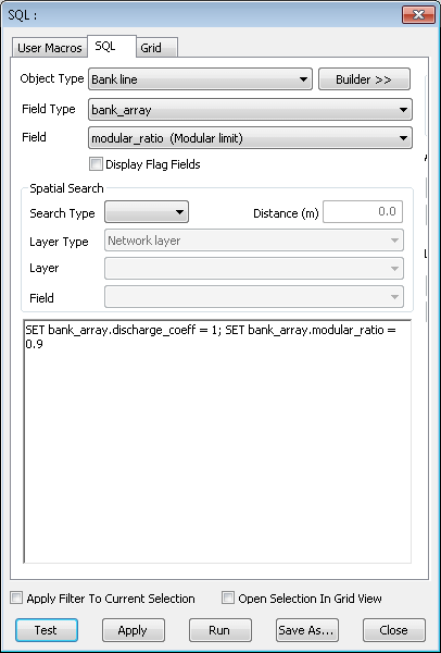
- The SQL dialog is displayed with the SQL page open.
- Select Bank line in the Object Type.
- Type in the SQL as shown in the screenshot below or select the correct field types and fields.
- Click on the Test button of the dialog to test the syntax before running the query.
- At this stage, you can run the query or save it prior to running. Please refer to the SQL dialog topic for more information. Click on Run.
- The query is run on the network currently open in the GeoPlan and the two parameters are updated accordingly. (You can re-open the Bank data of the Bank Line property sheet to check this is the case).
- Click on the
SQL Select button (
- If you want to manually add the values:
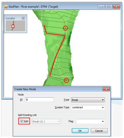
- The bank and the river reach are currently unconnected. The reach needs to encompass the bank line. As only a small section of the reach is being used in this example it is now necessary to add two more break nodes to define the river reach section that will have a bank incorporated.
- Set the
New Object type to
node and click on the
New Object tool ( ) of the
GeoPlan Tools toolbar and add a
Break node at each end, as shown below. Call the nodes A and B and ensure that the
Split check box is ticked in the
Create New Node dialog:
- To complete the process of making the bank part of the river reach select the bank line by using the
Selection tool () , then hold down the
CTRL key to add the river reach to the selection. Apply the
Build banks from selected lines option from the
Model | River Reach menu.
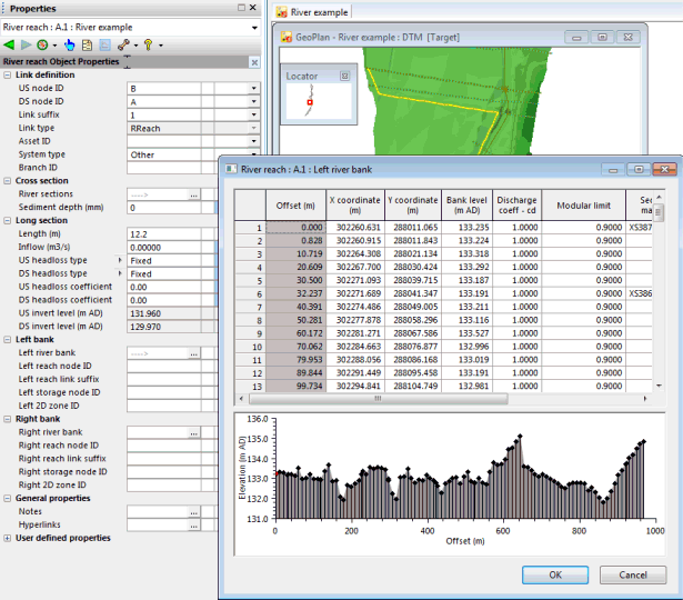
- You will notice that in the River Reach Property Sheet, the Left River Bank section will have a ---> in it, indicating that there is now bank data.
- Commit the changes made to the network:
- In the Explorer window, right-hand click on the River example network and select Commit changes to database.
- The Commit change to server dialog is displayed.
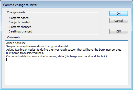
- Type in any notes as appropriate.
- Click OK to commit the changes and close the dialog.
- If a message is displayed asking you if you wish to validate the network at the same time as you are committing your changes, click on No for now. We will validate the network at a later stage.
When drawing the line, please ensure that the line and the river reach line do not intersect/touch.
A river may burst its banks and in InfoWorks ICM this can be modelled with ease. A river may spill onto a 2D mesh and flooding can be modelled from this point, or a bank may spill into a storage zone. For the purpose of this tutorial, we are going to add bank spill sections.
 Back to River Tutorial
main page.
Back to River Tutorial
main page.