Note: This stage assumes that you have started
InfoWorks ICM and that the
Explorer window is open, showing the
Adding a bridge network icon. You should complete the previous stages before starting this stage. If you want to work with the prepared example data, load the appropriate version of the network. For instructions on how to load the database, see
Opening the Example Database.
 Back to
previous stage.
Back to
previous stage.
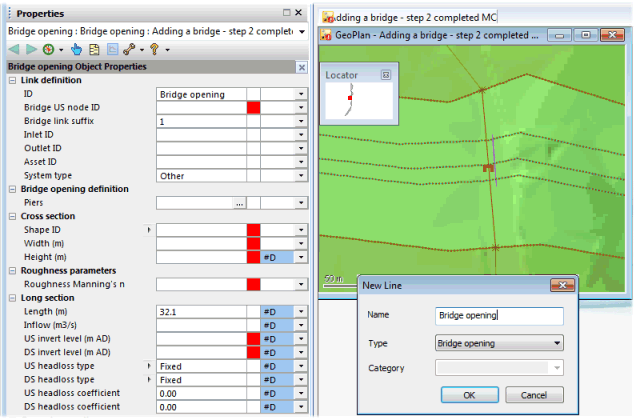
The Bridge Opening can be added by drawing a vertical line on the GeoPlan parallel to the bridge as shown below:
- Ensure that the Adding a bridge network and the DTM ground model are both open on the GeoPlan. Alternatively, if you have not completed the previous steps, please use the provided Adding a bridge- step 2 completed network as a starting point (in step 3 we validated the network and did not make any changes therefore there was nothing to commit).
- The validation process may have highlighted the bridge components on the GeoPlan. Click on the
Clear Selection button (
 ) of the
Selection toolbar.
) of the
Selection toolbar.
- Zoom in the bridge area by using the
Zoom in tool (
 ) of the
GeoPlan Tools toolbar.
) of the
GeoPlan Tools toolbar.
- Select
Line in the
New Object Type box and click on the
New Object button (
 ) of the GeoPlan Tools toolbar and draw a bank line as shown below.
- At the end, double-click to finish.
- The New Line dialog is displayed. Enter an appropriate name for the line (Bridge opening, for example).
- Select Bridge opening in the Type dropdown list. Click on OK.
- The bridge opening property sheet is displayed in the Object Properties Window.
- Enter the following data for the bridge opening:
Field
Value
Bridge US Node ID
Bridge1
Shape ID
Archsprung
Width
5m
Height
2m
Springing height
1.5m
Roughness Manning
0.038
Length
10m (replace existing value)
Upstream Invert Level
130.60m
Downstream Invert Level
130.60m
- Select the bridge and the opening on the GeoPlan with a combination of the
Selection button (
 ) and the
CTRL key and then select
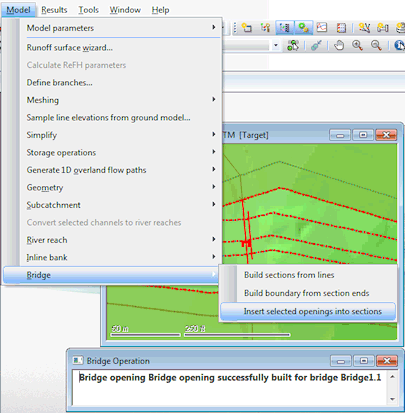
Model | Bridge | Insert selected openings into sections to complete the bridge structure. A report will confirm the bridge opening has been successfully added to the bridge. Check the details and close the report.
) and the
CTRL key and then select
Model | Bridge | Insert selected openings into sections to complete the bridge structure. A report will confirm the bridge opening has been successfully added to the bridge. Check the details and close the report.
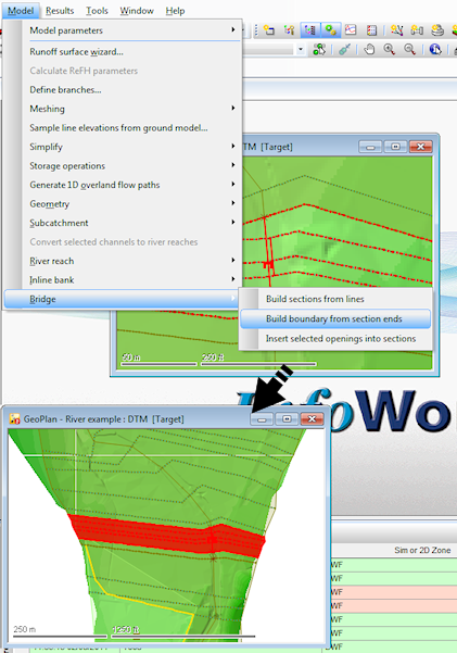
- The last step in building a bridge is to define a boundary for the bridge. Ensure the bridge is still selected in the GeoPlan (if required use the
Selection button () to re-select the bridge) and use
InfoWorks ICM's automatic boundary building tool : select
Bridge then
Build boundary from section ends from the
Model menu. A bounding polygon has been drawn for the selected bridge from the upstream and downstream bridge sections.
- Commit your changes and validate the network:
- In the Explorer window, right-hand click on the Adding a bridge network and select Commit changes to database.
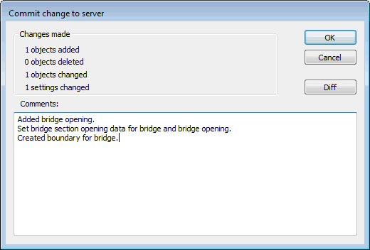
- The Commit change to server dialog is displayed.
- Type in any notes as appropriate.
- Click OK to commit the changes and close the dialog.
- Click Yes on the message asking you if you wish to validate the network at the same time as you are committing your changes.
- The Network Validation dialog is displayed.
- Click OK.
- This time, there should be no errors highlighted in the Output window. Close the Output window.
Note: When drawing the bridge opening, please ensure it is placed to the right of the bridge link and relatively close to it, as shown in the screenshot below.
The next section explains how to view bridges in InfoWorks ICM.
 Back to Bridge Tutorial
main page.
Back to Bridge Tutorial
main page.