Manholes are physical structures that connect pipes. They may be circular or rectangular in shape.
By default manhole's sync with their lowest connected connection.
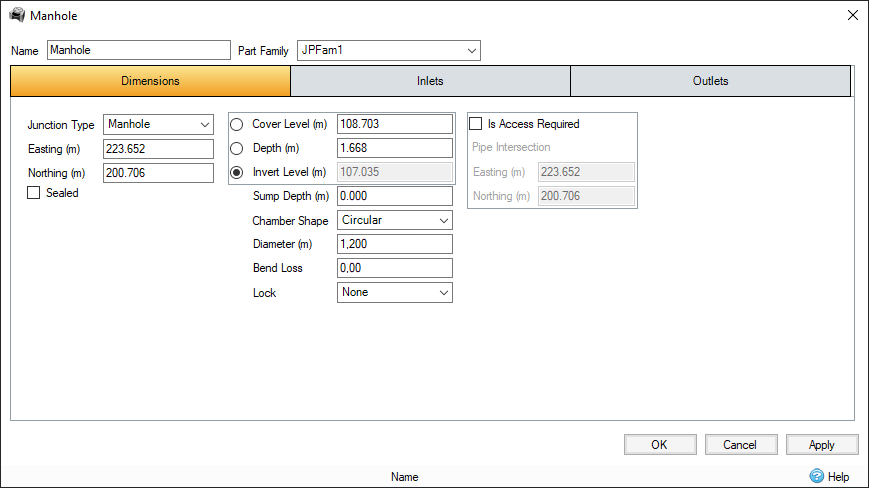
Name – Displays the name of the manhole.
Part Family – Select the part family associated with this manhole. For more information, see Part Families.
Dimensions
Junction Type – Select either Simple Junction or Manhole from the drop-down list.
Easting – The easting coordinate at the centre of the icon on Plan.
Northing – The northing coordinate at the centre of the icon on Plan.
Sealed – This tick box determines if the manhole is sealed or not. A sealed manhole will not flood during analysis.
The Cover Level, Depth and Invert Level are linked so that whichever parameter is highlighted with the radio button will be calculated from the other two variables.
Cover Level – The ground level (above datum) and the level where flooding is reported. An overflow or spillway crest Level may be specified at a lower Level as part of the outlet control details. If a Surface Data is present the Cover Level will automatically be picked up from the centre of the icon. Above the Cover Level, water will be stored above the ground and then allowed to drain back into the network. The default ponding area used for the flooded volume is 1000 m².
Depth – The depth of the manhole, i.e. the Cover Level minus the Invert Level, including sump (if applicable).
Invert Level – Represents the level (above datum) of the base of the manhole. If a sump is defined, it represents the level (above datum) of the bottom of the sump.
Sump Depth – Drop the Invert Level below the lowest incoming/outgoing connection level by this value.
Chamber Shape – Select the chamber shape as Circular or Rectangular to enable the dimensions to be set.
Diameter – The diameter is shown if Circular is selected as the Chamber Shape.
Length – The length is shown if Rectangular is selected as the Chamber Shape.
Width – The width is shown if Rectangular is selected as the Chamber Shape.
Bend Loss – The loss coefficient associated with energy losses that occur when flow enters a junction and then exits through an outgoing connection at a different angle. For more information, see Analysis of Junctions and Connections.
Lock – Determines the lock state.
None – No locking will occur.
Levels – Invert Levels will be locked so that automatic synchronisation will not occur and levels will not be adjusted through Network Design.
All – Invert Levels are locked so automatic synchronisation will not occur and the manhole will be excluded from Network Design completely.
Is Access Required – This tick box determines if the manhole requires access and therefore if an offset needs to be calculated. Ticking this box enables the pipe intersection fields.
Intersection Easting – The easting coordinate of where the incoming and outgoing connections meet inside the junction.
Intersection Northing – The northing coordinate of where the incoming and outgoing connections meet inside the junction.
Refer to the Inlets and Outlets pages for more details on these tabs.