|
|
The sections below describe the options available on the Takeoff dialog Dimensions and Options tabs for hanger patterns.
Takeoff Dialog Dimensions Tab
The following options are available on the Takeoff dialog Dimensions tab for hangers. Note that some of the options listed below are only available on certain types of hanger patterns.
Bearer: Specifies the length of the bearer for the hanger.
Bearer Extn: Specifies the length of the bearer extension for the hanger
Lap: Specifies the length dimension for the lap of the hanger part.
Arrow Length\Width\Offset\Rotation: Specifies dimensions for the arrow segment of the hanger part.
Length A\B: These dimensions are automatically calculated and set by the program. They represent the complete rod length, including the extensions above and below.
Supported Width\Depth: These dimensions are also automatically set. They are specified if the part you are cutting in the hanger to is insulated. They define the original pipe size (Width\Depth), but do not include any dimensions related to insulation.
Left & Right Rod Offsets: These options allow the user to control the position of the rods relative to the bearer. When set to Auto, the rod is positioned in the middle of the bearer extension. You can alternatively specify values to adjust this offset position relative to the bearer. The Same value lefts you set the Left side rode to use the same value as the Right side rod.
Takeoff Dialog Options Tab
The following options are available on the Takeoff dialog Options tab for hangers.
Profile: Specifies the shape of this item when displayed or measured as a profile; for example, round or oval.
Pipework: Specifies whether or not this item is categorized as a pipework item.
Block Thickness: Specifies the thickness of the Insulation Shield\block. This parameter can be associated with the Insulation Shield parameter described below.
Block Length: Specifies the length of the Insulation Shield\block. This parameter can be associated with the Insulation Shield parameter described below.
Number of Round Sections: Specifies the smoothness (or roundness) of round hangers. When this option is set to Auto, the Number of Round Sections option specified in Fittings Pattern Options, General tab, is used. Optionally, you can specify a value here. For more information, see Pattern Options.
Drop Rod Diameter: Specifies the diameter of the graphics drawn except , can be overwritten if Use Support Settings are set to Yes.
Bearer Width\Thickness: Specifies the width\thickness of the bearer.
Hex End: This option only applies to CID 1244 Roll Clevis Hanger types of hangers. It specifies whether or not to include hex-shaped ends at the ends of the bearer rod.
Roller Rod Diameter: Species the diameter of the roller rods, if a roller rod is included with the hanger type.
Oversized Item: Specifying Yes allows a rectangular bearer to be used on round duct or pipe by allowing user to specify the width and depth.
Area of Influence: This option allows you to specify an area (a circle shape) at the top of the drop rods that is considered the Area of Influence. This option is used in conjunction with the "A of I" (Area of Influence) options below. The Area of Influence indicates a circular exclusion zone that is used in coordination to identify an avoidance area, where other parts should not encroach. This is used in collision detection.
Export: Specifies which of the field points (Left, Right, All, None) associated with this part are exported to a file that can be used by an external robotic (field) point layout device. For more information, see Field Point Layout Support.
Front\Back\Left\Right Seismic Rod: Specifies how seismic rods are included on this part. Choices are No, Straight, Plus 45 Degrees.
Add Rod Size: Specifies whether or not to append the rod diameter to the description that is exported to a file intended for an external robotic field point layout device.
A of I: Filled Circle: Specifies whether or not the A of I circle is a solid object or not (Yes or No).
A of I: Circle Thickness: Specifies a thickness for the Area of Influence circle.
Use Support Settings: This option lets you define how hanger support drop rod diameters are specified. You can specify hanger support drop rod diameter on the pattern itself, by setting the Drop Rod Diameter field on the Takeoff dialog Options tab. When you want hanger support drop rods to be specified using this method, set the Use Support Settings option to No. Conversely, if you want the hanger support drop rod diameters to be specified using a support ancillary specification, set this option to Yes. For more information, see Controlling Support Rod Diameter with Ancillary Kits.
Point Load A\B: Specifies a user-defined value that can be extracted and associated with the model; for example, this can be used in reports, and or for loading calculations. For more information, see ADDSERVICETYPEBLOCK Command in the CADmep Command List.
Stretch Rods Separately: Specifies whether or not the rods can be stretched independently of the other rods associated with the hanger.
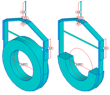
Insulation Shield: Specifies whether or not the Insulation Block is drawn (placed) fully wrapped-around the hanger, which would encompass the entire pipe or duct part, as shown on the left below, or when No is selected, the Insulation Shield is placed on, and only wraps around a portion (half) of the hanger, as shown below on the right.