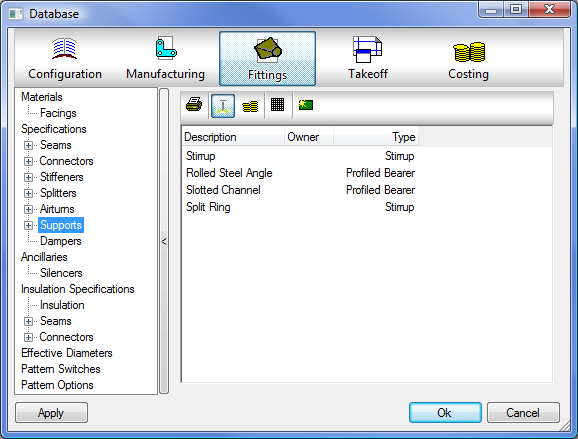
To edit or setup supports, click Database dialog, click Fittings
 Specifications
 Supports.

The Supports database is organized into two categories of settings: Manufacturing and Estimating. Both are accessed through the toolbar along the top by clicking either the Manufacturing icon
 or the Estimating icon
 .
.
Supports Toolbar
The Supports toolbar displays along the top of the dialog, in the right pane, and includes the following tools:

 Creates a printable report that includes the current support configuration and assignments.
 Clicking this icon display the Manufacturing data associated with Supports. This lists all the supports in the database and the Types that are assigned to each support. The Manufacturing view os the default view for this data.
 Clicking this icon display the Estimating data associated with Supports. This view provides the ability to assign a Labor rate for costing against any fabrication or installation time of the support ancillaries.
 Filter out Non User Data, allows the filtering of Autodesk-supplied content from the view.
 Creates a new support type. If an existing support is highlighted when clicking this icon, you are prompted to copy the existing support values.
Supports can be applied to straights or pipes using a specification. This is so the quantity and type of support can be defined based upon the item's dimensions. The supports are dictated by the length of duct or pipe entered against a support spacing requirement in the specification. The value on the spacing field identifies when the supports are to be assigned to the item. Each size of duct or pipe entered can therefore be given a support style, so that the heavier the duct or pipe is, alternative strengths of supports can be used at varying spacing requirements.
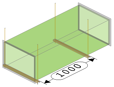
Using an item specification, you can assign the type of support against each breakpoint size, and additionally enter a spacing value for each instance. The diagram of the rectangular straight piece shown below dictates how the spacings are calculated. The first support is always at the zero length, and then based on the length entered, additionally added for each spacing value. The example below shows a 1000mm spacing on a 1500mm duct length. Therefore 2 supports will be included into the Straight Rate.

If desired, you can also create ancillary kits that define support rods of each type. For more information, see Controlling Support Rod Diameter with Ancillary Kits.
The other methods of using supports are through individual item files and using the Takeoff as Cut In procedure from the service button, or using Design Line Support Specifications for automatic population into the drawing.
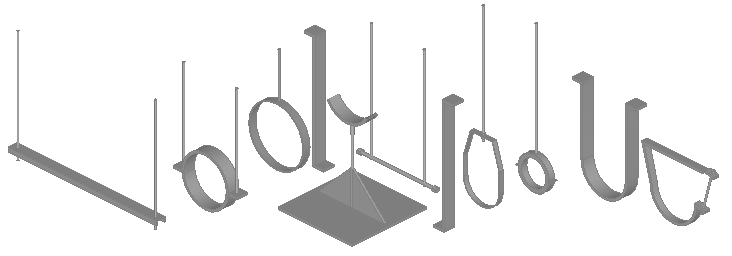
The support item file (CID 838) has a number of support options which allow you to choose from the various styles of the item for drawing. The following illustration shows some of these support style options displayed in a 3D view.

Assigning Supports to Items
Supports can be quantified and costed using the features available in ESTmep, as long as appropriate estimating data, such as supplier prices, codes and or installation times, are provided for the project. Furthermore, it is important to understand that there are two different methods that can be used in the configuration to automatically assign supports to items - you can either assign supports through the Item Specification, or you can assign supports through the Service Support Specification. Choosing one method, and staying consistent with using just one method throughout the configuration, reduces the risk of potentially duplicating the supports in the job or model. This ensures more reliable estimating data for support lengths and ancillary quantities. The two different methods are described further below.
- Assign Supports through the Item Specification: If desired, supports can be priced inclusively in the item's rate, under the Material breakdown itself. Using this method, there is no need to draw the supports visually in the view. This method of assigning supports is commonly used by estimators who, for analysis and quantifying purposes only, would need to assign in the Specification, a Support build up. See Support Types and Breakpoints for more information on this method.
- Assign Supports through the Service Support Specification: This method requires supports to be disabled in Item Specifications, and instead be allocated though Service Support Specifications. This method allows each hanger to be individually entered with their own item rate. See Support Specifications.