Setups for manufacturing
A setup defines what you want to machine and how. It is the first thing you create in the Manufacture workspace and is used to contain manufacturing operations. The things you specify when creating a setup vary depending on the type of manufacturing you want to do.

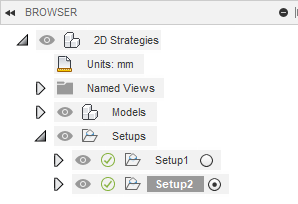
Example of a project with two setups.
Subtractive
For subtractive manufacturing (milling, turning or mill/turn, and cutting), in general, you specify:
- The machine and operation type that you want to use.
- The work coordinate system’s orientation and origin location.
- The models that represent the parts you want to make.
- The stock to define the size and dimensions of the workpiece you want to machine away.
- The settings for the post processor.
Additive
For additive manufacturing, in general, you specify:
- The machine and operation type that you want to use.
- The print settings for the chosen machine.
- The models that represent the parts you want to make.
- How to arrange the parts within the additive machine’s build volume.
Machine and operation type
When you create a setup, you choose a machine, which automatically selects the operation type. The operation type defines the manufacturing process.
| Operation type | Machine |
|---|---|
| Milling | Mill |
| Turning or Mill/Turn | Lathe |
| Cutting | Waterjet, laser, wire EM, plasma cutter |
| Additive | 3D printer |
For additive manufacturing, when you choose a machine you must also choose a print setting. A print setting is a collection of parameters associated with an additive machine and is specific to the bulk, raw material used in the additive manufacturing process. A print setting influences how an additive toolpath gets generated. The list of parameters in a print setting depends on the additive capability of the associated machine.
Work coordinate system
For subtractive manufacturing, the work coordinate system (WCS) defines the orientation of the workpiece and establishes the location of the origin. The origin is the point from which all operations are referenced.
Model
The model defines what is being made. By default, all the models on the canvas are automatically selected. If you have multiple models representing multiple parts, you can individually select which models you want included in the setup. You can also use the model to define the origin location of the work coordinate system.
For subtractive manufacturing, you can also specify any model as a fixture. A fixture is a structure that holds or supports the workpiece during machining, for example, a vice, a clamp, or a chuck. Collisions with fixtures are highlighted during stock simulation.
Stock
For subtractive manufacturing, the stock represents the size and shape of the workpiece from which a part is machined. Defining the stock lets you visualize the raw material being removed during the manufacturing process when you simulate operations. The size of the stock is automatically determined based on the model, but you can define it manually.
Post processing
For subtractive manufacturing, there are several options for post processing the operations in a setup, including letting you set a numerical work offset. The work offset corresponds to a specific G-code on a machine tool (for example, 0 or 1 might correspond to G54) and is the distance between the work coordinate system and the machine-tool coordinate system.