Activity 2: Specify a design space
In this activity, you specify the design space by determining which geometry to include in generative design process (preserve geometry) and which geometry exclude from it (obstacle geometry).

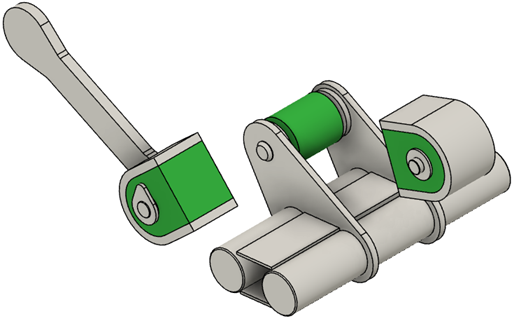
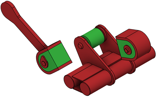
The Front Loader opened (left) and the model with the geometry types assigned (right).
Prerequisites
- Activity 1 is complete.
Steps
Assign a preserve geometry to the components created in Inventor.
Note: The preserve geometry is a type of geometry that you apply to a body you want to include in the final shape of your design. In our example, such bodies (bodies from 4 to 6) are the connection points so we want to keep them to be able to attach the design to other objects in the model. For more information, see Preserve geometry.- On the Define tab, click Design Space > Preserve Geometry
 .
. - To expand the list of components, in the Browser, under Model Components, expand GD Study > Bodies.
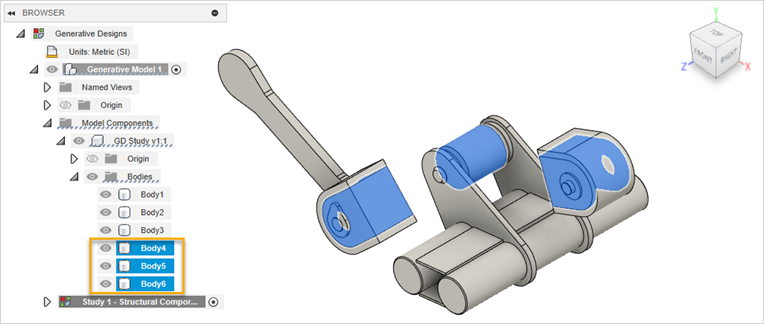
- In the Browser, select the bodies highlighted in blue (bodies from 4 to 6) as shown in the following image.

Note: On the canvas, you can see that these components are highlighted too. - In the Preserve Geometry dialog, click OK.
The bodies display in green on the canvas.
- To verify that 3 bodies are assigned as preserve geometries in your design, in the Browser, under Study 1, expand Preserve Geometry.
Tip: To modify, mouse over the Preserve Geometry node in the Browser, and then click .
.
- On the Define tab, click Design Space > Preserve Geometry
Assign an obstacle geometry to the components.
Note: The obstacle geometry is a type of geometry that you apply to a body you want to exclude from the final shape of your design. It represents empty spaces where material isn’t created during the generation of outcomes. In our example, these regions (bodies from 1 to 3) need to be free from material because of the movement of the part. For more information, see Obstacle geometry.- On the Define tab, click Design Space > Obstacle Geometry
 .
. - To expand the list of components, in the Browser, under Model Components, expand GD Study > Bodies.
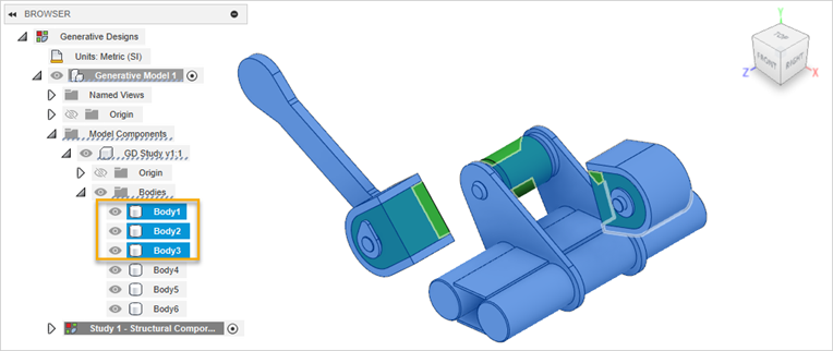
- In the Browser, select the bodies highlighted in blue (bodies from 1 to 3) as shown in the following image.

Note: On the canvas, you can see that these components are highlighted too. - In the Obstacle Geometry dialog, click OK.
The bodies display in red on the canvas.
- To verify that 3 bodies are assigned as obstacle geometries in your design, in the Browser, under Study 1, expand Obstacle Geometry.
Tip: To modify, mouse over the Obstacle Geometry node in the Browser, and then click .
.
- On the Define tab, click Design Space > Obstacle Geometry
Activity 2 summary
In this activity, you specified the design space by assigning the geometry types to the Front Loader model.