Activity 3: Apply constraints and loads
In this activity, you specify design conditions by applying constraints and loads to the selected geometry. You create five different load cases.

The Front Loader model with the geometry types assigned (left) and the model with constraints and loads applied (right).
Prerequisites
- Activity 2 is complete.
Steps
Apply a fixed constraint to the interior faces of the Body6 component. For more information, see Fixed constraint.
Note: Use constraint to define how the design interacts with the objects not included in the model. In this place (interior faces of the Body6 component), the design will be attached to the Loader model.- To hide the obstacles on the canvas, in the Browser, click
 next to the Obstacle Geometry node.
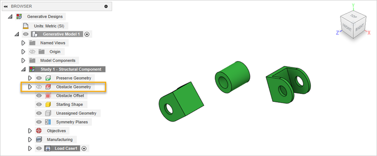
- On the Define tab, click Design Conditions > Structural Constraints
 .
.
Warning: You can apply constraints to preserve geometries only. - In the Structural Constraints dialog, verify that Fixed constraint is selected.
- On the canvas, select the faces highlighted in blue as shown in the following image. To select these faces, you can zoom in the area marked in orange.
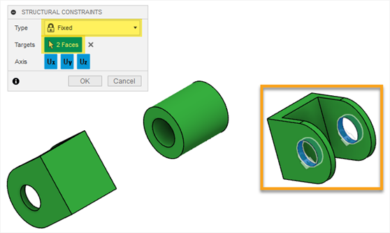
Note: The padlock icons display on the selected faces. - In the Structural Constraints dialog, click OK.
- To verify that the constraint is applied correctly, in the Browser, expand Load Case1 > Constraints.
Tip: To modify the applied constraint, do one of the following:- Mouse over it in the browser, and then click
 .
. - On the canvas, double-click the padlock icon.
- Mouse over it in the browser, and then click
- To hide the obstacles on the canvas, in the Browser, click
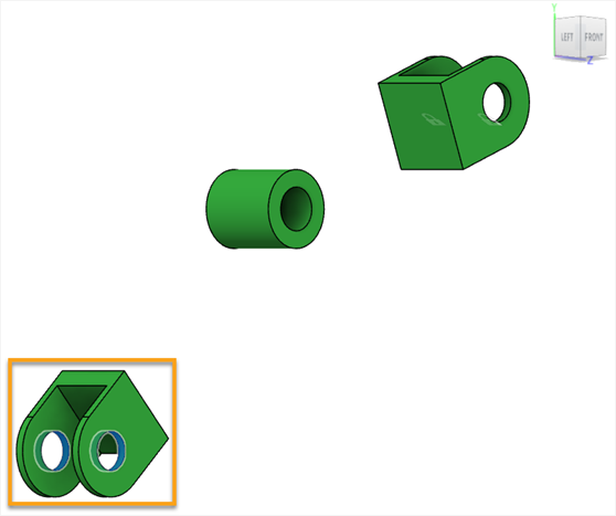
Apply a force load to the interior faces of the Body4 component. For more information, see Force load.
Note: Loads are the external forces that cause the design to work, but can also bend or break it. The design should be strong enough to resist the loads you apply. You need to apply loads that best match what the design will be exposed to in the real world. The loader will carry the load so you have to apply the force that will simulate it.- On the Define tab, click Design Conditions > Structural Loads
 .
.
Warning: You can apply loads to preserve geometries only. - In the Structural Loads dialog, verify that Force load is selected.
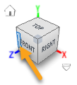
- To change the current view, click the left edge of the ViewCube.
- On the canvas, select the faces highlighted in blue as shown in the following image. To select these faces, you can zoom in the area marked in orange.
- In the Structural Loads dialog, for Direction Type click the Vectors (x, y, z) icon
 .
. - In the Fy input field, enter -1600.
The arrows display on the selected faces as shown in the following image.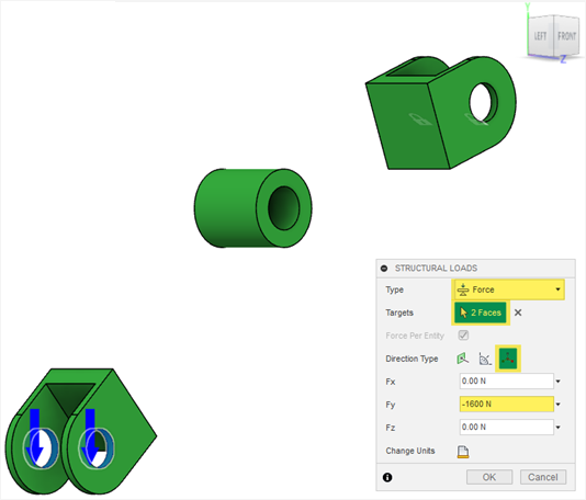
- Click OK.
- To verify that the force load is applied properly, expand Load Case1 > Loads.
Tip: To modify the applied load, do one of the following:- Mouse over it in the browser, and then click
 .
. - On the canvas, double-click the arrow icon.
- Mouse over it in the browser, and then click
- On the Define tab, click Design Conditions > Structural Loads
Clone the Load Case1.
Tip: If you are creating load cases that are similar but, for example, the loads need to apply in an opposite direction, then it is quicker to clone and edit a load case, instead of creating a new one.- In the Browser, right-click Load Case1 and select Clone Load Case from the context menu.
Load Case2 appears in the Browser. - Repeat the previous step to create the additional load case.
Load Case3 appears in the Browser.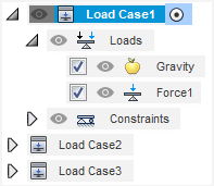
- In the Browser, right-click Load Case1 and select Clone Load Case from the context menu.
Modify the Force2 load for Load Case2.
- Double-click Load Case2 to activate this load case.
Load Case2 is highlighted in blue in the Browser. - In the Browser, expand Load Case2 > Loads.
- Mouse over Force2, and then click
 .
. - In the Fy input field, delete the - sign to change the force direction.
The arrows display on the selected face as shown in the following image.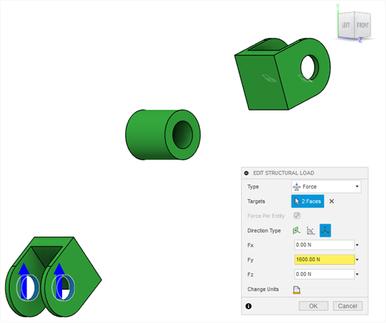
- Click OK.
- Double-click Load Case2 to activate this load case.
Modify the Force3 load and the Fixed3 constraint for Load Case3.
- In the Browser, right-click Load Case3, and select Activate Load Case from the context menu.
Load Case3 is highlighted in blue in the Browser. - In the Browser, expand Load Case3 > Loads.
- Select Force3, and then click
 .
. - In the Fy input field, enter 10000.
The arrows display on the selected face as in the following image.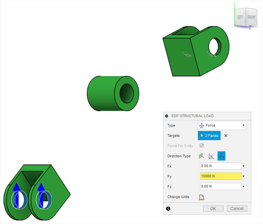
- Click OK.
- In the Browser, expand Load Case3 > Constraints.
- Select Fixed3, and then click
 .
. - In the Structural Constraints dialog, in the Targets field, click X to remove the selected faces.
- On the canvas, select the face highlighted in blue as shown in the following image. To select the face, you can zoom in the area marked in orange.
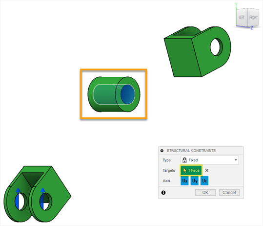
Note: The padlock icon displays on the selected face. - In the Structural Constraints dialog, click OK.
- In the Browser, right-click Load Case3, and select Activate Load Case from the context menu.
Clone the Load Case3 and modify the Force4 load for Load Case4.
- In the Browser, right-click Load Case3 and select Clone Load Case from the context menu.
Load Case4 appears in the Browser. - Double-click Load Case4 to activate this load case.
Load Case4 is highlighted in blue in the Browser. - In the Browser, expand Load Case4 > Loads.
- Mouse over Force4, and then click
 .
. - In the Fy input field, type the - sign to change the force direction.
The arrows display on the selected faces in opposite direction as shown in the following image.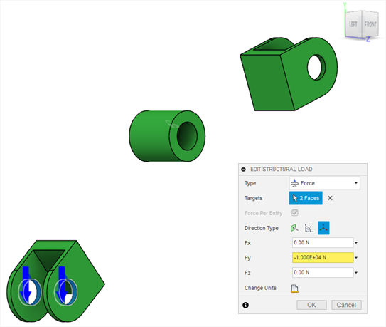
- Click OK.
- In the Browser, right-click Load Case3 and select Clone Load Case from the context menu.
Create a new load case and apply a fixed constraint to the interior faces of the Body4 component.
- In the Browser, right-click Load Case4 and select New Load Case from the context menu.
Load Case5 appears in the Browser. - On the Define tab, click Design Conditions > Structural Constraints
 .
.
- In the Structural Constraints dialog, verify that Fixed constraint is selected.
- On the canvas, select the faces highlighted in blue as shown in the following image. To select these faces, you can zoom in the area marked in orange.
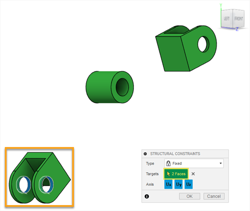
Note: The padlock icons display on the selected faces. - In the Structural Constraints dialog, click OK.
- In the Browser, right-click Load Case4 and select New Load Case from the context menu.
Apply a force load to the interior faces of the Body6 component for Load Case5.
- On the Define tab, click Design Conditions > Structural Loads
 .
. - In the Structural Loads dialog, verify that Force load is selected.
- To return to the Home view, move the cursor over the ViewCube, and click
 Home.
Home. - On the canvas, select the faces highlighted in blue as shown in the following image. To select these faces, you can zoom in the area marked in orange.
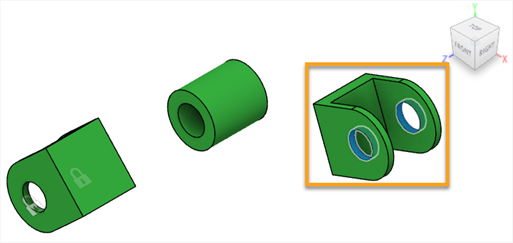
- In the Structural Loads dialog, for Direction Type click the Vectors (x, y, z) icon
 .
. - In the Fy input field, enter -1600.
The arrows display on the selected faces as shown in the following image.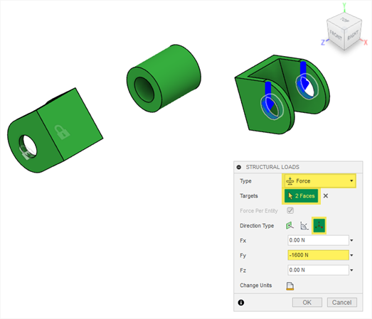
- Click OK.
- To display the hidden obstacles on the canvas, in the Browser, click
 next to the Obstacle Geometry node.
 - In the Browser, double-click to activate each of the load cases in order to verify that they match the following image.
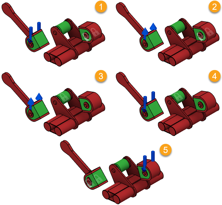
- On the Define tab, click Design Conditions > Structural Loads
Activity 3 summary
In this activity, you specified design conditions by applying constraints and loads to the selected geometry.