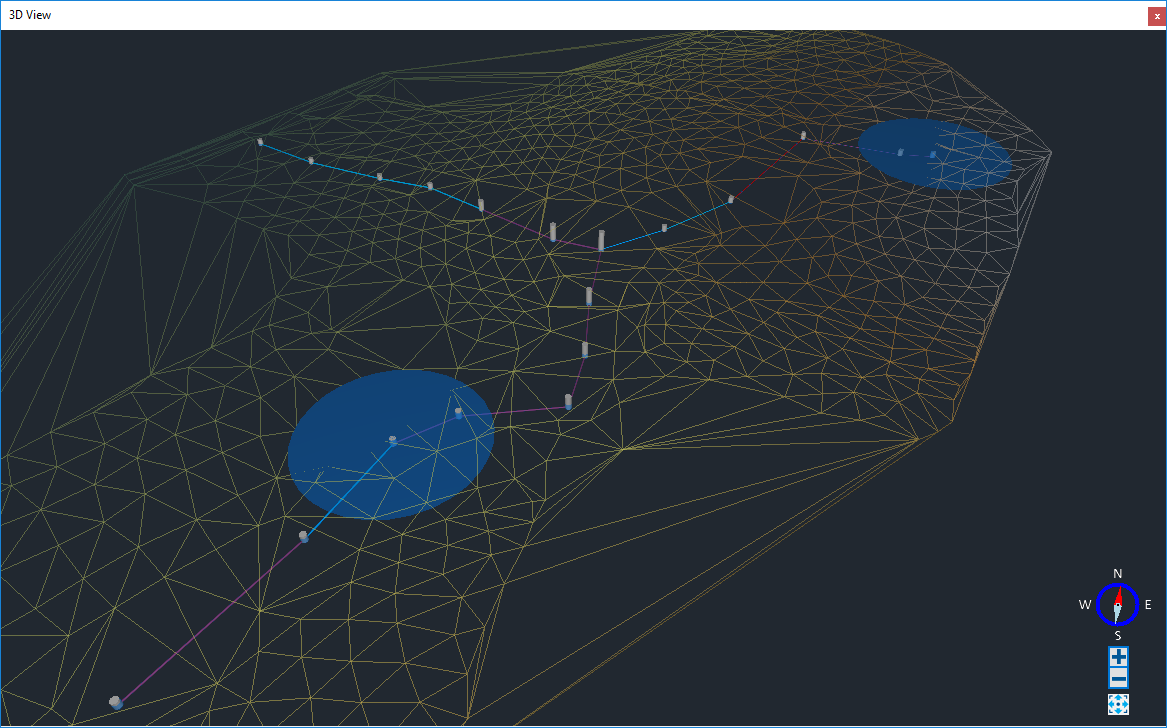
The 3D window displays the locations and dimensions of Stormwater Controls (SWCs), Junctions, Connections, Surface Data, and Overland Flows in three dimensions.

Special Cases
Notional Connections are displayed simply as a line between the exceedance / cover elevation of the connected junctions / SWCs.
Simple Junctions are displayed as a translucent sphere. The size and height of this sphere is determined by the incoming and outgoing connections.
Bypass Connections are displayed identically to other connections in 3D, unlike on Plan.
Inlets and Outlets are not displayed in 3D.
Underdrains are not displayed in 3D on SWCs with custom outlines.
Stormwater Controls that contain multiple smaller structures (Cellular Storage, Chambers, Dry Well) are rendered as cylinders, cuboids or prisms, rather than as a collection of smaller structures, if the position of each smaller structure cannot be determined.
Water Elevations
To avoid a visual error known as Z fighting, when water dimensions are set to a dimension of an object, a small offset is applied. Because offset is always applied at the bottom and sides of objects, the volume of the displayed water is not exact. The water elevation is kept exact where possible (see Specific Implications column in the table below).
In the following table, an object is labelled as not flooding if the water elevation obtained from analysis can never be greater than the objects cover / crown.
| Top | Floods | Flooded area | Example | Where is offset added? | Specific Implications |
| Open | No | - | Rectangular channel | Bottom and side edges only. The top of the water is exactly the elevation obtained from analysis. |
|
| Open | Yes | Matches top area | Pond | Bottom and side edges only. The top of the water is exactly the elevation obtained from analysis. | |
| Closed | No | - | Pipe | Top, bottom and side edges. |
Water elevation is not exact, only the water shape, i.e., the water in a pipe is only a completed cylinder when the water elevation matches the diameter of the pipe, but this cylinder is larger than the pipe. |
| Closed | Yes | Matches top area | Porous Paving | Bottom and side edges only. The top of the water is exactly the elevation obtained from analysis. |
If the water elevation is very close to the top of the closed object, there will be Z fighting. |
| Closed | Yes | Set area | Manhole (unless sealed) | Bottom and side edges of the non-flooded area only. The top of the water is exactly the elevation obtained from analysis, regardless of flooding. If the object is flooding, the flooded area is exactly the set area. |
If the water elevation is very close to the top of the closed object, there will be Z fighting. |
Controls
Animation
Video controls appear on the form when results have been generated, which allows you to view their water elevation animation. If more than the result form is open, the water elevation animation will be synchronized between them, as well as any open profile forms and SWC item results forms. The same video controls also appear on the Status Bar .

Keyboard and Mouse Controls
The camera points at a focal point in the center of the screen, which can be controlled in the following ways:
- Move - This moves the focal point, and by extension the camera.
- Turn - This turns the camera, moving it at the same time so it continues to point directly at the focal point.
- Zoom - This moves the camera towards or away from the focal point.
The following keyboard and mouse inputs can be used to control the camera in the 3D window.
| Action | Keyboard Input | Mouse Input |
| Move Forward | W / Up Arrow |
Holding the middle-mouse button and moving the mouse forward or backwards will move will move the design in the direction of the mouse movement. |
| Move Backwards | S / Down Arrow | |
| Move Left | A / Left arrow | Holding the middle-mouse button or left mouse button and moving the mouse left or right will move will move the design in the direction of the mouse movement. |
| Move Right | D / Right Arrow | |
| Move Up | E / Page Up |
Holding the left-mouse button and moving the mouse will move the design up when the mouse is moved forward and down when moved backwards. |
| Move Down | Q / Page Down | |
| Faster Movement | Hold Left Shift | Not Applicable |
| Slower Movement | Hold Left Shift and Left Control | |
| Turn Up | I |
Holding the right-mouse button and moving the mouse will rotate the camera in the direction of the mouse movement. |
| Turn Down | K | |
| Turn Left | J | |
| Turn Right | L | |
| Zoom In | + | Scrolling the mouse wheel forward and backward will move the camera in towards the focal point and out away from the focal point respectively. |
| Zoom Out | - |
Navigation Controls

The directional arrow on the compass control will show you which direction the camera is pointing.
Clicking on one of the cardinal directions (N, E, S or W) will move the camera to that side of the focal point. e.g. Clicking N will move the camera north of the current focal point, and point the camera south.
The
 and
and
 buttons will zoom the camera in and out, moving the camera towards and away from the camera respectively.
Pressing the
Extents
 button will update the view to the full site extents.
Settings
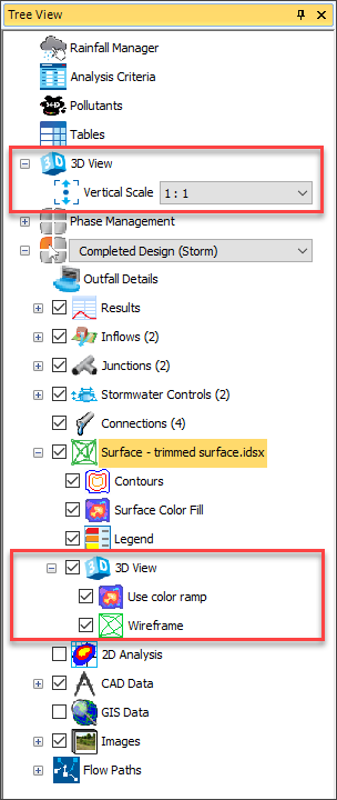
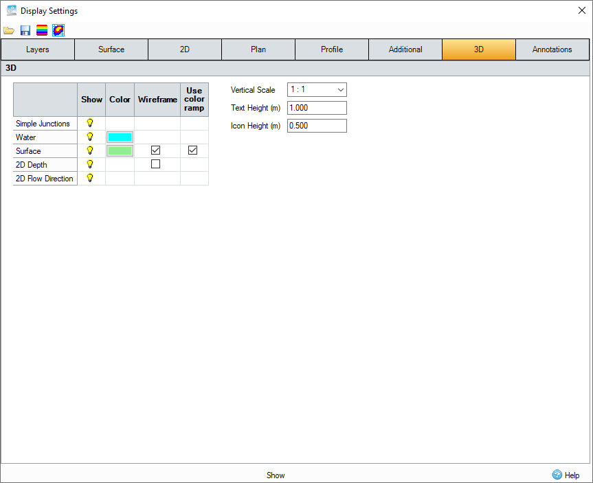
Settings specific to 3D are available under 3D sections in both the Tree View and Display Settings. There is a 3D node in the tree view underneath the surface node, which can be used to quickly update 3D surface settings.
3D Settings on Tree View

3D Settings on Display Settings

Shared Settings
The following settings are shared with other areas of the software.
- Show, Color, and Select settings from the Layers tab of the Display Settings are used by both the Plan and 3D windows.
- The Color setting from the Additional tab of the Display Settings are used by both the Plan and 3D windows.
- Settings from the Surface tab of the Display Settings are used by the surface on both the Plan and 3D windows.
Analysis
The shape representing an object in the 3D window is not always identical to the shape used in analysis. Analysis is performed on either an equivalent or simpler geometry. See the following pages for more information on analysis: Analysis, Analysis of Junctions and Connections, Analysis of Stormwater Controls.
Junctions
- Manholes - Modelled similarly in both 3D and analysis.
- Simple junctions - Modelled as translucent spheres in 3D. Simple junctions in analysis are described in detail here.
Connections
- Physical connections - Modelled similarly in both 3D and analysis.
- Notional connections - Modelled as lines in 3D. Notional connections in analysis are described in detail here.
Stormwater Controls
- Rectangular outlines - Modelled in 3D and analysis primarily as cuboids. When side slope is applied, either directly or as a result of a depth-area-volume table, only the two sides are sloped, and the two ends remain vertical.
- Circular outlines - Modelled similarly in both 3D and analysis.
- Free form outlines - Modelled with the given outline in 3D, converted to an approximate rectangular outline in analysis.
- Long Slope - Modelled in 3D by skewing the SWC. Vertical sides remain vertical at any slope. Rotated in analysis, so that the angle between base and sides are the same at any slope.
Switching Video Cards to Solve Problems in 3D
If there are problems in the 3D view such as the visual error known as Z-fighting or other graphical issues, the problem may be solved by switching from the on-board Video Card to the dedicated Video Card (if available). See the instructions below on how to swap for both Nvidia and AMD Video Cards:
To switch to an Nvidia video card:
- Open the Nvidia Control Panel. You can do this by right-clicking on the desktop or you can find the option within the notification area of the Taskbar.
- Select Manage 3D Settings under the 3D Settings section.
- Click on the Program Settings tab and select the program you want to choose a graphics card for from the drop-down list.
- Select the 'preferred graphics processor' in the drop-down list. If you want to use the dedicated graphics card, select High-performance Nvidia processor.
- Restart InfoDrainage and the dedicated Video Card should now be used.
To switch to an AMD video card:
- Right-click on the Desktop and select AMD Radeon Software (may be called Radeon Catalyst Control Center in older versions).
- Go to Graphics > PowerPlay - Set Plugged In and Battery to Maximum Performance. Click Apply.
- Go to Graphics > 3D and move the slider across to Performance so it is set for Optimal Performance. Click Apply. (May not be applicable for all models)
- If your Radeon Software has the Switchable Graphics tab, go there and browse to locate InfoDrainage.exe and set it for High Performance. Click Apply.
- Restart InfoDrainage and the dedicated Video Card should now be used.