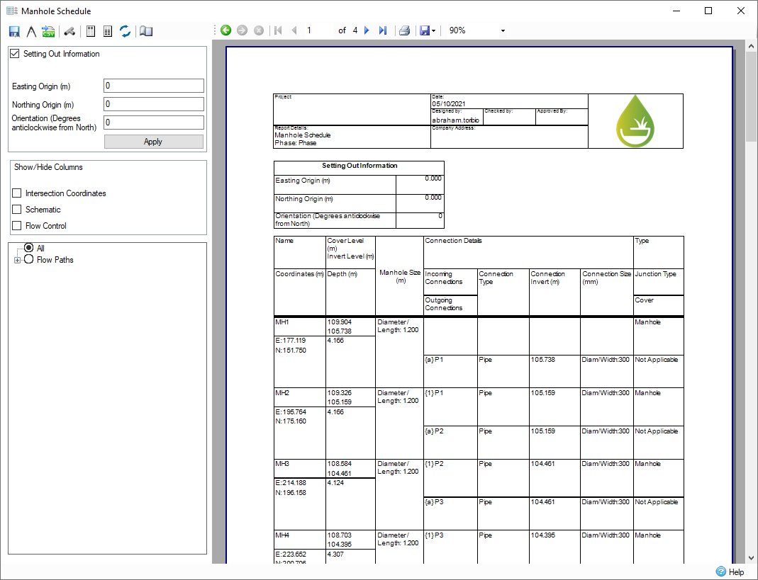
The Manhole Schedule displays a breakdown of the junctions in the current phase, their incoming and outgoing connections, and their respective flow control.
The Manhole Schedule form can be accessed from the Results Ribbon, when there is at least one junction in the network. Opening the form will display all manholes currently in the phase. The Schedule can then be refined to show different flow paths. You also have the option to view Simple Junctions, which is hidden by default.
The Manhole Schedule can be exported to CAD with the layers, and table size configurable using CAD options. Additionally the Schedule can be exported to CSV.
The information on the Schedule will be automatically updated when a change is made on the plan. For example, if a manhole is deleted, the Schedule will be automatically updated with the change.
Manhole Schedule Form
The junctions are displayed as one continuous table, where each junction has its own three row block. If the Schedule flows to another page, the headers are repeated for ease of reading. The Manhole Schedule displays a number of attributes about the junction including the connections incoming and outgoing, and the flow control(s) currently being used.

In situations where the junction does not have any incoming or outgoing connections, the cell will be left blank. If the flow control is Free Discharge, then an Invert Elevation is not displayed either.
As there are rectangular and circular manholes, as well as simple junctions that all have their own attributes, the Manhole Schedule can look slightly different for each of these types/junctions. The same applies to the various connections. All attributes are listed below:
Attributes:
- Name
- Coordinates - Easting and Northing
- Intersection - Easting and Northing
- Cover Elevation
- Invert Elevation
- Depth
- Manhole Schematic
- Manhole Size
- Incoming Connections
- Outgoing Connections
- Connection Type
- Connection Invert
- Connection Size
- Junction Type
- Cover
- Flow Control Type
- Flow Control IL
A few differences in these attributes can be found depending on the type of junction and connection. These may include:
Circular Manhole:
- Manhole Size displays only Diameter/Length
Rectangular Manhole:
- Does not have Intersection Points
- Displays Diameter/Length and Width
Simple Junction:
- Does not have Intersection Points
- Does not have Cover Elevation, Invert Elevation or Depth
- Does not have a Size
Pipe:
- Only has Diameter/Width as Size
Triangular Channel:
- Only has Height as Size
All other Hydraulic Connections:
- Have Diameter/Base Width and Height as Size
All Notional Connections:
- Does not have Invert and Connection Size - displays "N/A "
The Manhole Schematic is an accurate representation of the manhole and its connections. Each connection is labelled with a number for incoming connections and a letter for outgoing connections. The direction of the connection on the schedule matches with that of the plan. For a circular manhole, the incoming and outgoing connections meet at the intersection point. This means that if Manhole Sizing has occurred and produced an offset, the schematic will show that same offset. If the intersection point is located outside of the manhole, the schematic will not show the connections, and instead show a cross through the Manhole with the message "pipe(s) located outside of manhole ".
A circular manhole is represented by a circle for the junction and an inner filled-in circle to represent the center point. A rectangular manhole shows a rectangle with the same ratio as its length and width, with a filled-in circle representing its center. A simple junction is represented as only the center circle.
The junction type shows what junction is being displayed. This may be a manhole or simple junction, and it displays if the junction requires access or is sealed. These are set on the Manhole form, where access and sealed can be toggled using checkboxes.
Currently the Cover field is not used and displays Not Applicable for each junction.
Manhole Schedule Toolbar
The toolbar can be used to export the Schedule, as well as enable/disable the display of Simple Junctions.

Export to CAD - This functionality exports the Schedule to CAD either as a .DWG or .DXF in versions 2010, 2013 and 2018. This will export the schedule as it is currently displayed with the colours specified in the CAD Options.
CAD Options - Opens a form that allows certain options to be configured that will be applied when the Schedule is exported to CAD.
Export to CSV - Exports the Schedule to a .CSV file. Currently, the exported .CSV shows columns read from left to right of the Manhole Schedule.
Show Simple Junctions - Enables the display of Simple Junctions, which is disabled by default. Upon clicking this button, the schedule will update with Simple Junctions.
Header Font - Opens dialog box to allow changing of font, font style, text size, and script for the Hard Copy Heading.
Report Font - Opens dialog box to allow changing of font, font style, text size, and script for the Manhole Schedule report.
Reset Font - Resets both the header and report font back to default.
Edit Page Settings - Opens dialog box to allow page settings to be changed. This is linked to the local page setting in file print.
Setting Out Information
The Setting Out Information controls the ability to swap between true and site coordinates, which is then reflected on the Manhole Schedule. By default, this section is disabled and therefore true coordinates are used. This can be changed by checking the checkbox in this section to swap to site coordinates. By adjusting the Easting Origin and the Northing Origin, each junctions coordinates, and intersection points, are adjusted to match the newly specified site origin point. Adjusting the orientation rotates the site from true north that changes the junction coordinates, and intersection points, as well as rotating the schematic on the schedule to show that the connections are now entering the junction at a different angle. These changes are applied once you click the Apply button, in which the form will then refresh with the updated coordinates. The inputted values are saved and applied to the schedule whenever the form is opened even on different phases. In order to swap back to true coordinates, and reset the setting out information, clear the checkbox, the schedule will update back to the true coordinates without the Apply button needing to be click.

Show/Hide Columns
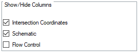
The Show/Hide Columns controls the information that is displayed on the Manhole Schedule. By default, all information is displayed and therefore each box will be checked. Each checkbox can be unchecked and the relevant information will no longer be shown on the Manhole Schedule. There are three options that can be turned off: Intersection Coordinates, Schematic, and the Flow Control columns.

Flow Path Selection
The default selection for the Manhole Schedule is to display all junctions on the site. This can be configured to display all flow paths, as well as allow individual flow paths to be viewed.

The Manhole Schedule will update automatically when the check boxes are changed or when a flow path is created or deleted on the plan.
If the selection contains only simple junctions and they are not enabled, then the page will simply display No Valid Junctions.
CAD Options
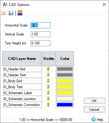
The CAD Options form is used to set up the CAD Export options. The colours can be modified for each layer. The layers can be turned off using the lightbulb icons. Scaling factors can be selected for both horizontal and vertical axes, and a text height can be applied to ensure all text is a suitable height.

The settings can be saved and re-loaded using the toolbar icons. The toolbar also contains a Reset button to revert all colors and settings to their default values.
Navigation
The navigation toolbar is used to navigate through each page of the Manhole Schedule by using the arrows or by entering a page number.

Additionally, page settings can be changed from this toolbar. You can also edit the properties, such as the page size and orientation. You can also access the Parameters button, where you can edit the font size.
The Save icon allows you to export the currently drawn set of reports to a variety of formats (CSV export does not give accurate headers, use the export to CSV button on the toolbar instead):
- CSV
- Excel
- RTF
- TIFF
- Web Archive
- XPS document
The Schedule can also be printed from this toolbar and the current zoom level can be selected.