
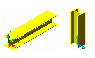
Straight beams are created in the 3D model relative to the current user coordinate system (UCS) by entering one starting point and one end point. A beam is created according to the selected section.
The current user coordinate system (UCS) determines the position of the sections' main axes (working line): the beam web runs in the Z direction of the UCS, (i.e. the top of the section is in the Z direction).
To create a simple section, use the Section classes flyout on the Beams panel of the Objects tab.
Access the command
On the Objects tab  Beams panel Sections flyout.
Command line: _astm4crbeammfc
- Select a suitable UCS.
- On the Objects tab Beams panel, select the desired section from the corresponding flyout.
- Specify the start point of the beam system axis.
- Specify the end point of the beam system axis.
- The straight beam is created.
The properties dialog box appears.
Create a steel column
Without a UCS in the right plane, a steel column of a default length can be created by entering a point. The point defines the start point of the section's main axes.
Access the command
On the Objects tab Beams panel , click
 (Column).
Command line: _AstM4CommGridAxes