
User setup
The user_setup sub-compound defines the structure of a module. This includes the local hierarchy of controls and joints, their rest transforms, control shapes and attributes, as well as the rules for how entities are parented, both within the module and between modules.
You can find some nodes designed specifically for use in this section in the Rigging::Module::Setup namespace in either the Tab menu or Node Library.
When authoring this section, ensure that the edit_mode module parameter is enabled so the setup is recomputed when the graph is evaluated.
Overview
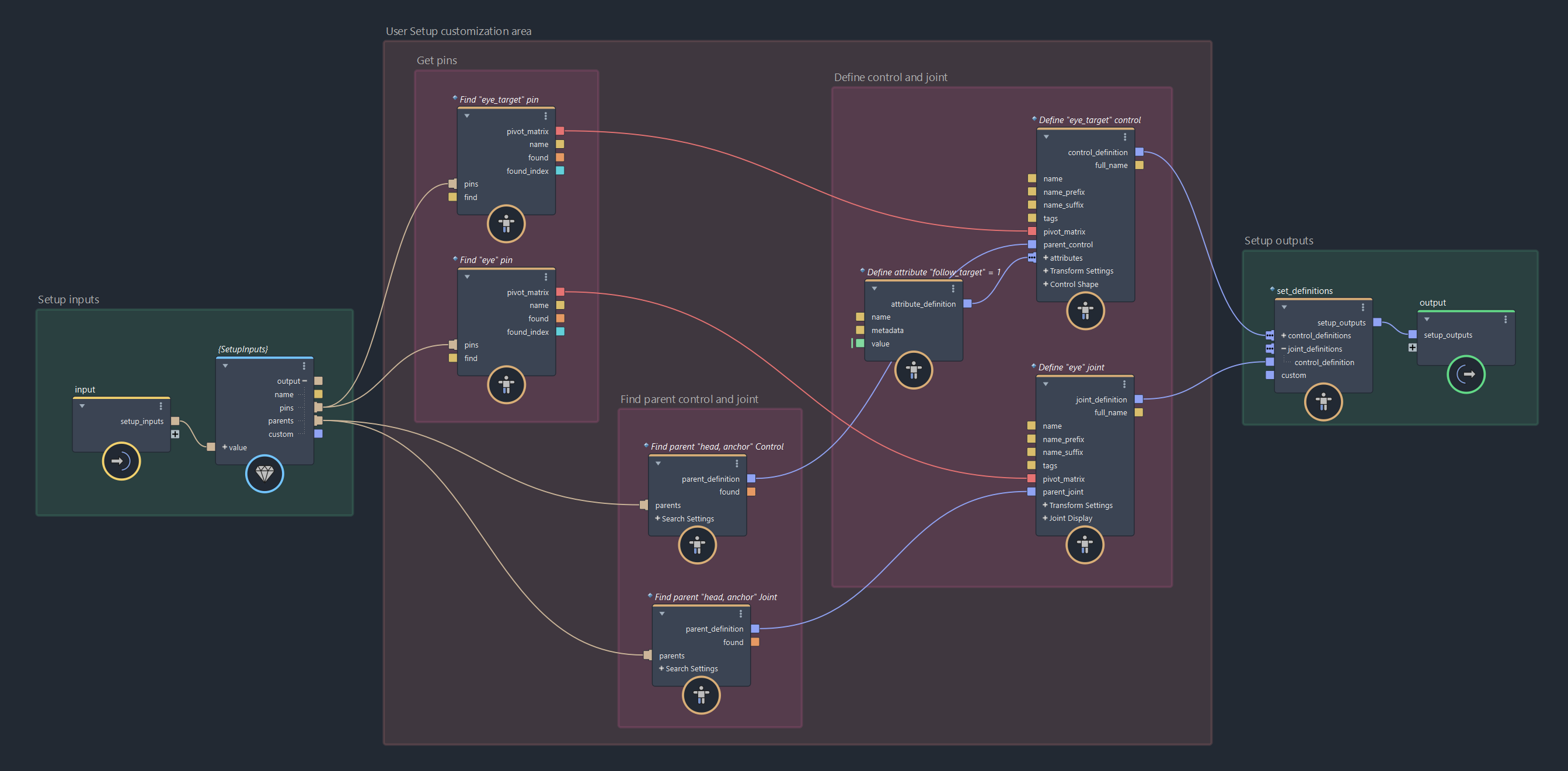
In this section, you are responsible for declaring the structural content of the module. You are provided with input data, such as pins, names, and parents, and you are expected to define the controls and joints that the module will generate.
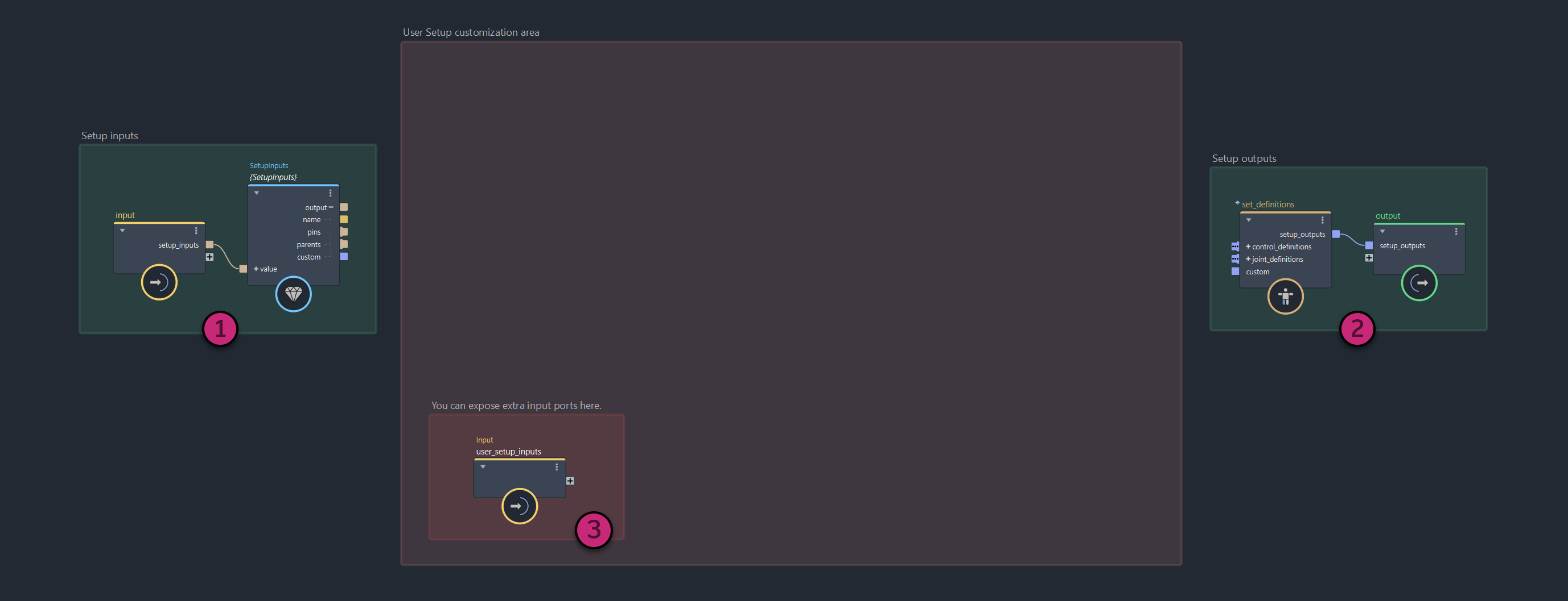
The user_setup layout includes:
SetupInputs(1): A struct that aggregates setup-related input data containing thename(this module's name), thepinsarray, theparentsarray, andcustom.set_definitions(2): A node where you connect the control and joint definitions created in this module. Definitions connected to it will be used to generate entities for this module.user_setup_inputs(3): An input node to expose parameters at the top level of the module so that you can control youruser_setuplogic from there. You can create as many input nodes as needed.
Defining Controls and Joints
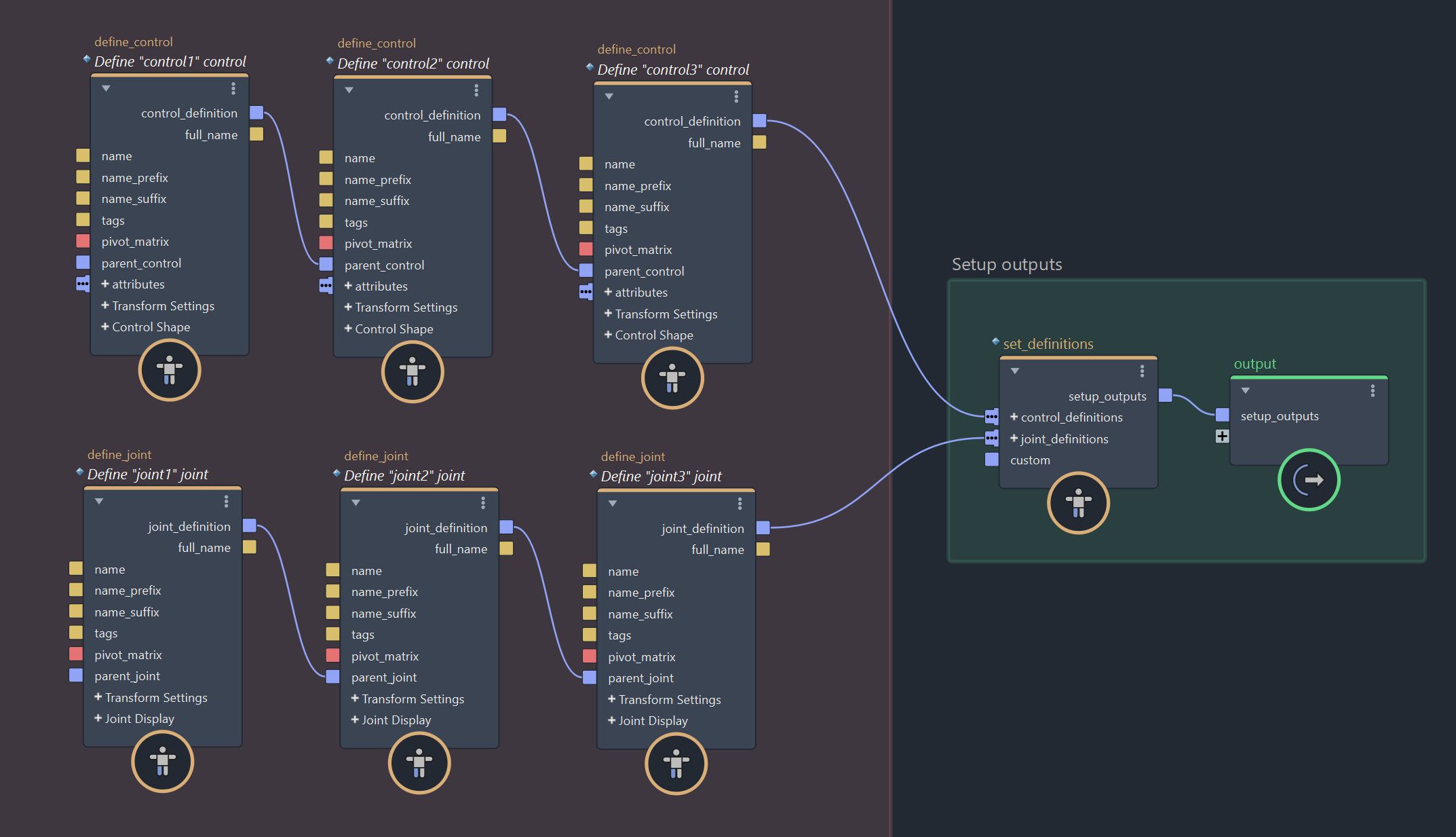
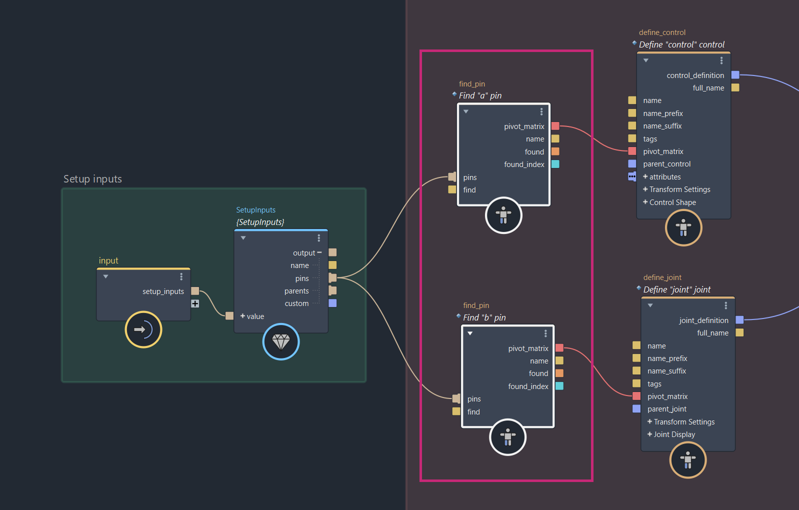
Controls and joints can be defined using the dedicated define_control and define_joint nodes.
These nodes can be daisy-chained to create simple chains (e.g. FK limbs), or arranged into any kind of hierarchy. The only requirement is that each resulting branch is connected to its respective port on the set_definitions node.
While define_control and define_joint serve different purposes, they follow a similar structure:
- The
name,name_prefixandname_suffixports allow you to generate entity names procedurally. For example, to use the module's name as a prefix for all controls and joints, connect thenameoutput fromSetupInputsto thename_prefixof alldefine_controlanddefine_jointnodes . - The
tagsport allows you to add comma separated strings on an entity for identification. These can be useful when querying entities later usingfind_*nodes likefind_parent(inside theuser_setupsub-compound), but alsofind_transformorfind_all_transforms(insideuser_animationsub-compound). - The
pivot_matrixport is what defines the rest transformation of an entity in world space. You can plug a pin's pivot matrix directly here, or compute one manually from other pin data. - The
parent_control/parent_jointports define the parent relationship for this entity. These inputs can accept outputs from otherdefine_control/define_jointnodes, or afind_parentnode if you want to parent this entity under one from a parent module. - The Transform Settings port group contains parameters that allow you to set the rotation order and lock individual transform components. Note that these settings are not used within Bifrost, but are passed through to the host application to be apply to on created rig objects.
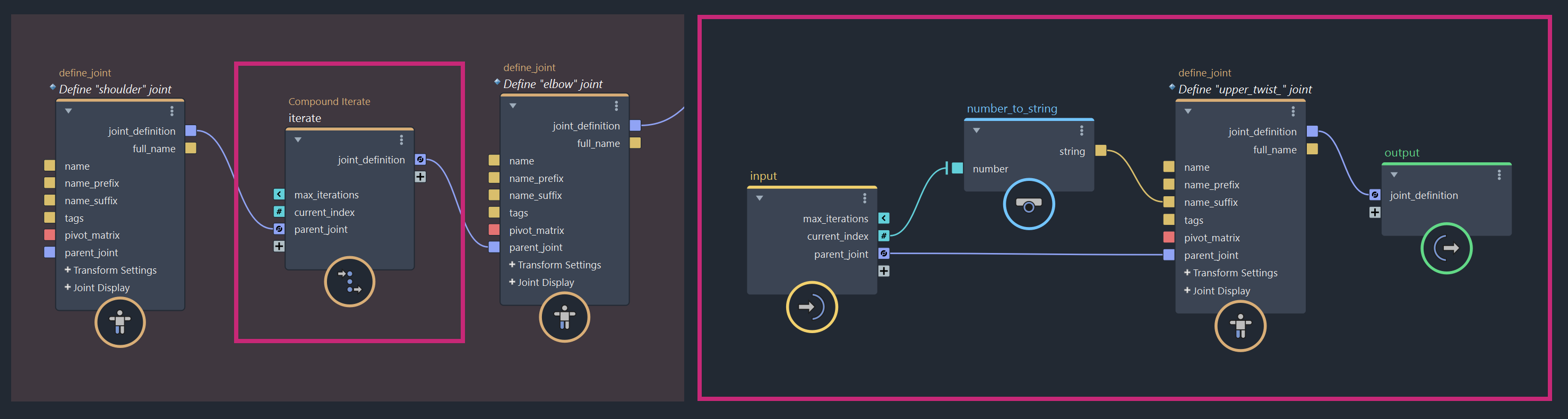
The define_control and define_joint nodes do not need to be created manually for every entity you want to generate — you can also use them inside loops to generate entities procedurally. In the example below, a variable number of upper twist joints are created between a shoulder and an elbow joint, resulting in a joint chain with 2 + n joints, where n is controlled by the max_iterations port on the iterate node.
Using Pins
To define the pivot_matrix of the controls and joints you create, you'll typically use pins, which serve as guide transforms for rig entities.
Pins are passed through the module's inputs port as an array of named matrices and are accessible via the SetupInputs struct.
The recommended way to query pin data is to use the dedicated find_pin or find_all_pins nodes. The workflow is as follows:
Connecting Pin Data
To start, connect the pins output from the SetupInputs struct to the pins input of each find_pin or find_all_pins node you intend to use. This gives each node access to the pins data passed on a module's inputs port.
Specifying a Search
Use the find port to specify which pin(s) to retrieve. This input accepts a search expression that filters pin names. The search supports wildcards (*) and negation (!). For example:
- "
*neck*" will match any pin whose name contains "neck". - "
head*" will match any pin whose name starts with "head". - "
*neck* !*head*" will match any pin whose name contains "neck" but not "head". - "
head" will match any pin named exactly "head".
The first pin matching the expression is returned by find_pin, while find_all_pins returns all matches as an array.
Using Pin Pivot Matrices
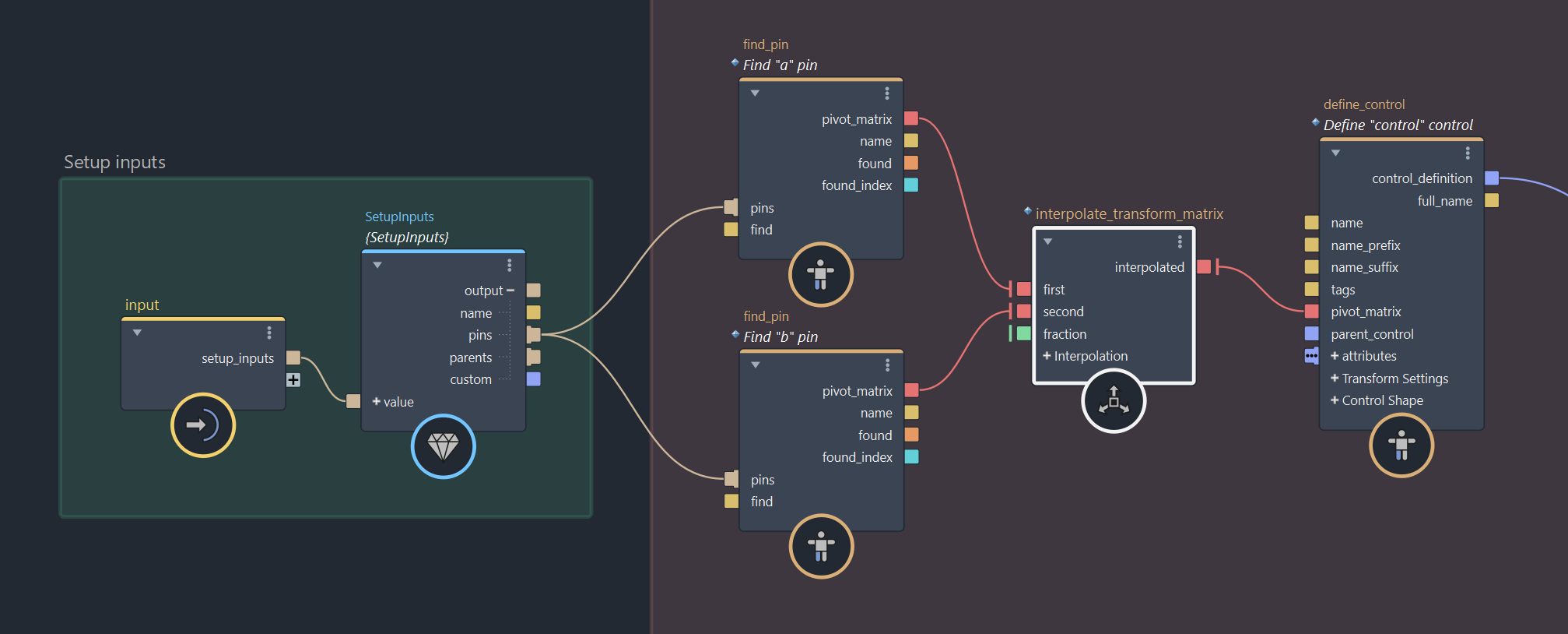
The pivot matrices from pins are typically used as the rest transforms of controls and joints in the module.
You can connect the pivot_matrix output from a find_pin node to the corresponding input on a define_control or define_joint node.
There is no requirement for a one-to-one relationship between pins and the entities you define. You are free to use the same pin on one or multiple entities, and even repurpose its matrix as needed.
For more procedural setups, you can compute new pivot matrices from pins. For example, you can interpolate between two pins to place twist joints, intermediate controls, or other procedurally generated entities.
Parent-Child Relationship Between Modules
The user_setup sub-compound is also where you define how the module's controls and joints are parented under entities from connected upstream modules.
This is done using the parents input on the SetupInputs struct, which contains the same data passed to the module's top-level parents port.
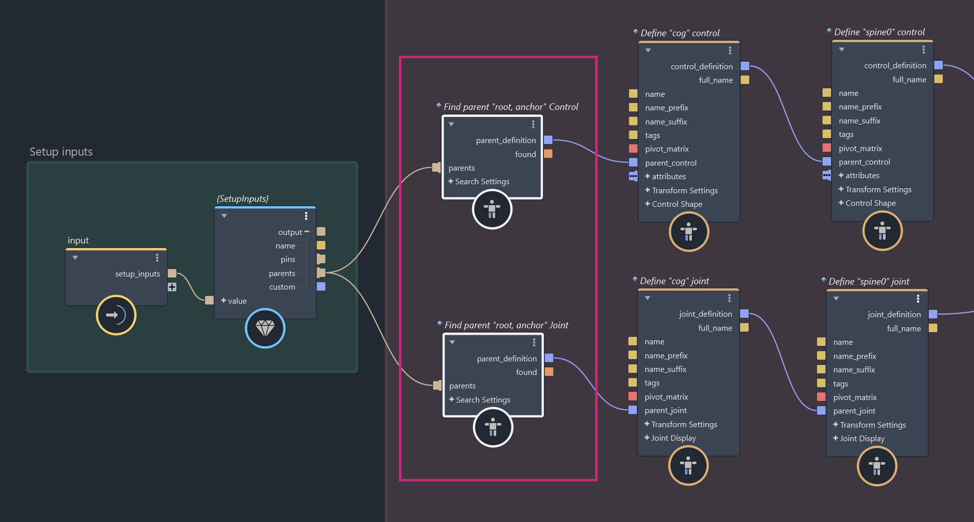
You can use the dedicated find_parent node to query a specific parent entity. Its output can then be connected directly to the parent_control or parent_joint port of a control or joint definition to establish a cross-module parent-child relationship.
A control can never be parented under a joint, and a joint can never be parented under a control. Make sure to always match entity kinds when establishing parenting.
Connecting Parent Data
To start, connect the parents output from the SetupInputs struct to the parents input of each find_parent node you intend to use. This gives each node access to all parent entities provided by connected upstream modules.
Specifying a Search
First, set the kind to indicate the type of entity you want to search for. This should be either Control or Joint.
Next, set the search_method to determine how the parent will be searched. You can choose to search By Name or By Tags.
When using the By Name method, the find string is interpreted as a search expression that matches parent entity names. Wildcards (*) and negation (!) are supported. Examples:
- "
foot" will match the first parent named exactly "foot" - "
leg_*" will match the first parent whose name starts with "leg_" - "
*hand*" will match the first parent whose name contains "hand"
When using the By Tags method, the find string is interpreted as a comma-separated list of tags. This is useful when you want to define standardized parenting rules without relying on specific naming conventions.
For example, specifying "root, anchor, hook" will search for a entity that matches one or more of those tags.
- If
find_all_tagsis disabled, the first parent containing any of the listed tags will match. - If
find_all_tagsis enabled, the first parent containing all of the listed tags will match.
Connect the Parent Definition to Control and Joint Definitions
All that's left is to connect the parent_definition output from your find_parent node to the parent_control port of a define_control node, or the parent_joint port of a define_joint node.
If a matching parent is found, the entity will be parented under it and inherit its transformation automatically.
Control Attributes
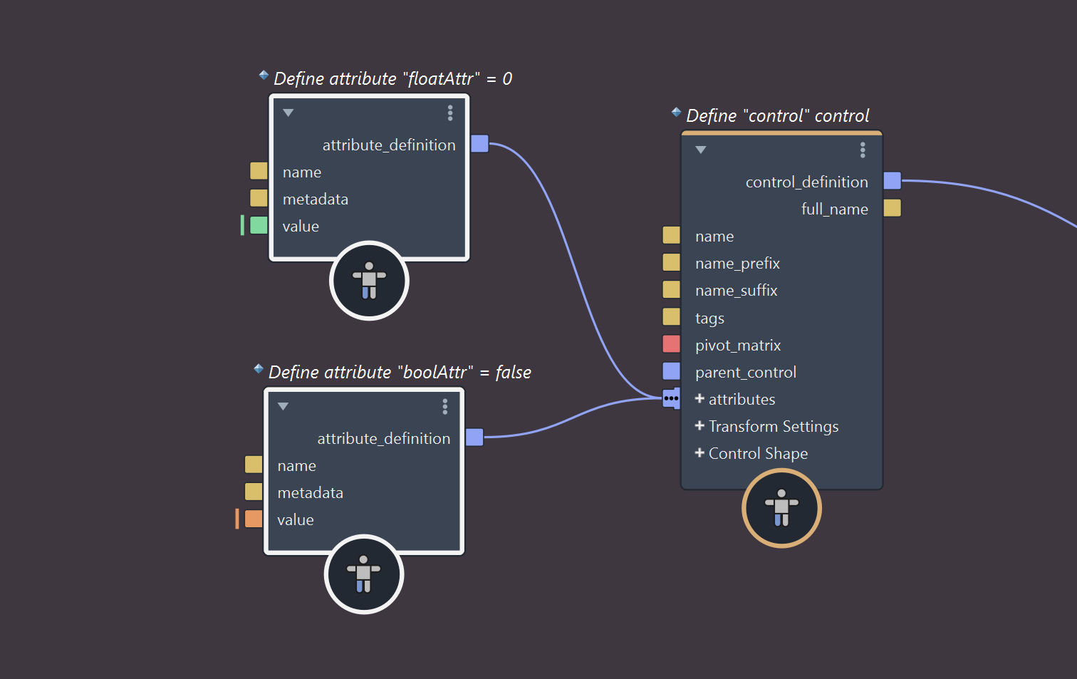
You can add custom attributes to control definitions using the define_attribute node.
These attributes will be created on the host application's control objects and allow animators to drive aspects of a module's transformation logic inside user_animation sub-compound, directly from the rig.
All attribute definitions are passed through the module's outputs port, including their names, types, metadata, and default values, to create the actual attributes on control objects in the host application.
At runtime, the attribute values from the host controls are passed back into the module through the inputs port and made available inside the user_animation sub-compound, to be used to affect your transformation logic.
Creating Attribute Definitions
While you can create and connect define_attribute nodes manually, the fastest way is to right-click on the attributes port of a define_control node and choose Create Node > define_attribute.
You can add as many attributes as needed to a single control. The value port determines both the type and default value of the attribute. Four data types are supported: float, float3, int, and bool.
Attribute Metadata
You can also specify metadata to customize the behavior and appearance of attributes in the host application.
Metadata can be used to lock attributes, set value ranges, or define enums. Multiple metadata entries can be combined using commas.
Common metadata options include:
Min: Sets the minimum value allowed (for float, float3, or int)Max: Sets the maximum value allowed (for float, float3, or int)Enum=[one, two, ...]: Defines a combo box for int attributes using a comma-separated list of keysLock: Locks the attributeHide: Hides the attribute.NonKeyable: Makes the attribute non-keyable.
Control Shapes
Each defined control can have a shape attached to it, which is used to visually represent the control in the viewport.
Built-in Shapes
The define_control node includes a list of built-in shapes, which you can select via the shape port's dropdown list.
These shapes are standard strand-based primitives commonly used in rigging. If you need an invisible control, simply set the shape to None.
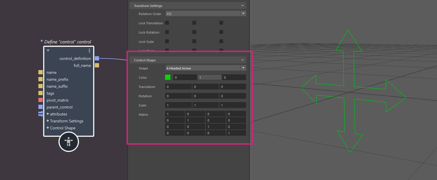
Shape Offsets
By default, the shape is placed at the control's location and inherits its transformation.
You can adjust the shape using the translation, rotation, and scale ports. These apply an offset to the shape's geometry only, and do not affect the control's actual transform.
For even more control, you can use the matrix port to specify a custom rest location for the shape. The shape still follows the control's transform. This matrix affects only its rest location.
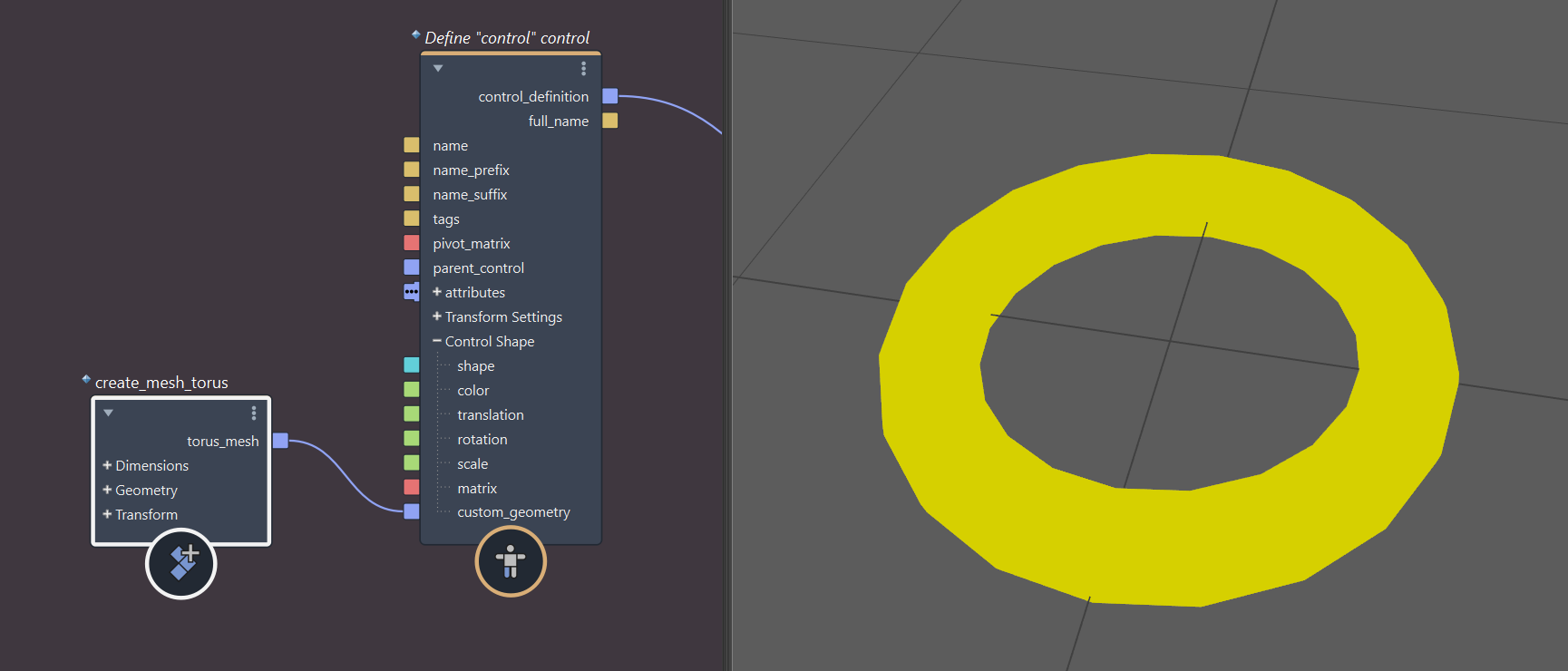
Custom Shape Geometry
If you need a more specialized shape, you can use custom geometry instead of a built-in shape. Both mesh and strand geometries are supported.
To assign custom geometry, connect it to the custom_geometry port on the define_control node. This overrides the selected built-in shape and draws the provided geometry instead.
Custom geometries should be authored as primitives in local space. They also support color and offsets, just like built-in shapes.
Custom Setup Data
The user_setup sub-compound allows you to get and set custom setup data as Bifrost objects.
On the SetupInputs struct, the custom port provides access to the object passed through inputs.setup.custom. You can get values from this object using get_property and use them as part of your setup logic.
You can also generate and store your own custom setup data. To do this, use set_property to set values to a Bifrost object, then connect that object to the custom port of the set_definitions node.
Custom setup data is available within the user_animation sub-compound, where it can be used for animation logic. It is also passed through the module's outputs port, allowing access by downstream modules and the host application.
Example Use Case
The example below demonstrates how custom setup data can be read and written independently.
Input data is accessed from SetupInputs.custom(1) using get_property nodes (2), in this case to assign custom shape geometry to controls.
Separately, some neural network weights and biases are read from file and stored using set_property nodes (3), then passed to set_definitions (4) for later use in user_animation.
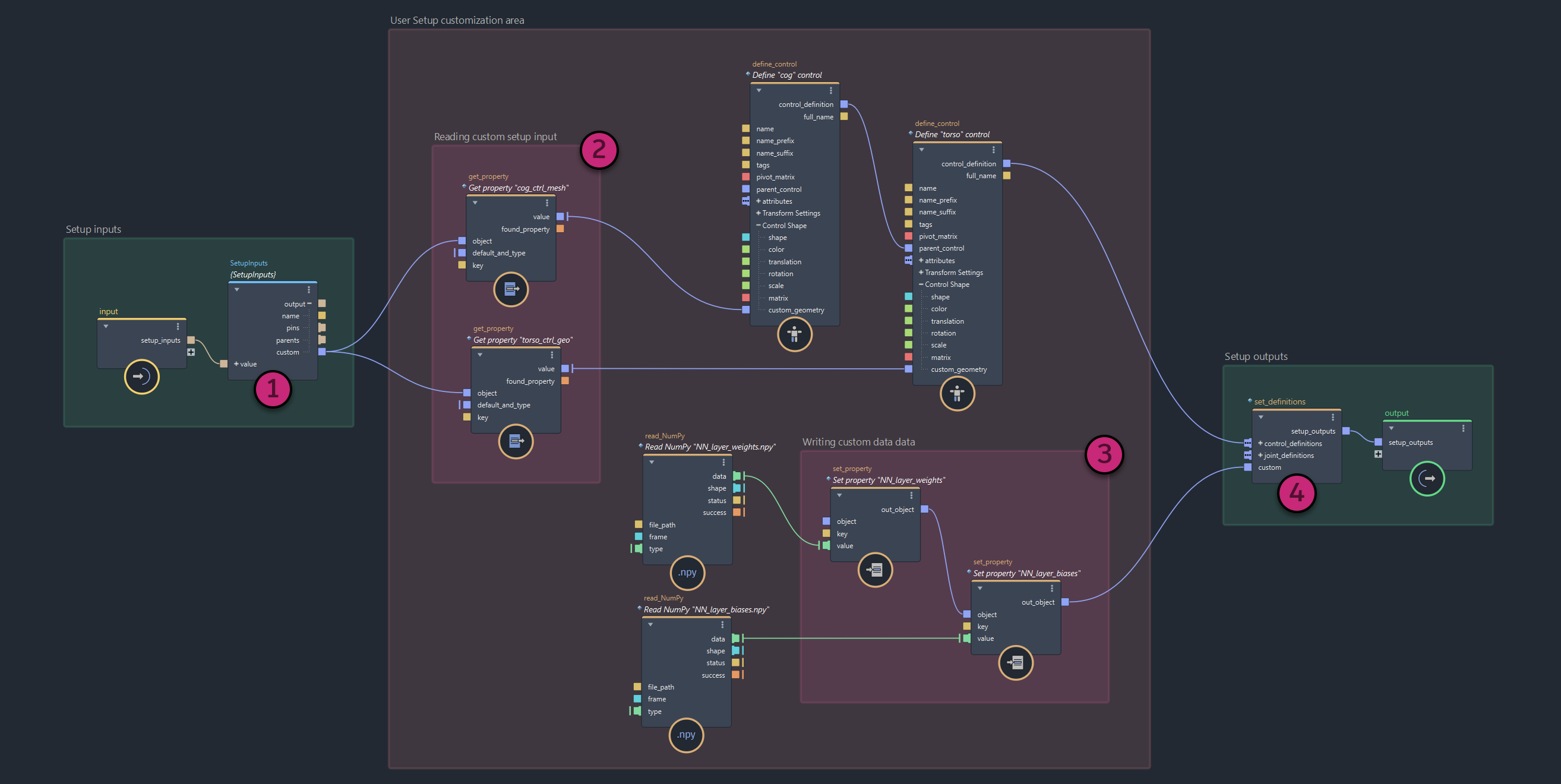
This is just one example. The same workflow can be used to handle any kind of custom data.