
You can set up different styles to display and label projections and crossings in section views.
Projected objects in section views use the following styles:
- Projected COGO point objects use standard point styles. You can specify a different style to use in section view, or you can specify <Use Object> to use the same style that is used in plan view.
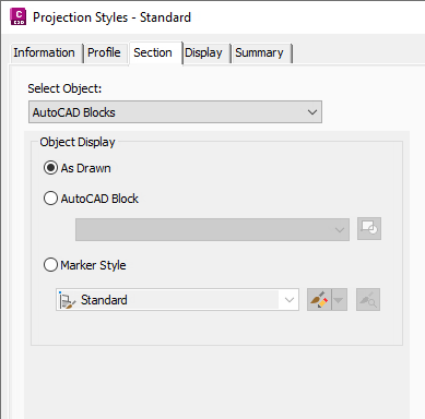
- Projected AutoCAD objects and multi-view blocks use projection styles. Projection styles are multipurpose styles and can be found in the General
 Multipurpose Styles Projection Styles collection on the Settings tab in Toolspace. Use the Section tab to configure the display settings for section view.
- For label styles, projected objects use projection label styles which can be found in the Section View Label Styles Projection collection on the Settings tab in Toolspace.
Crossing objects in section views use the following styles:
- Crossing COGO point objects use standard point styles. You can specify a different style to use in section view, or you can specify <Use Object> to use the same style that is used in plan view.
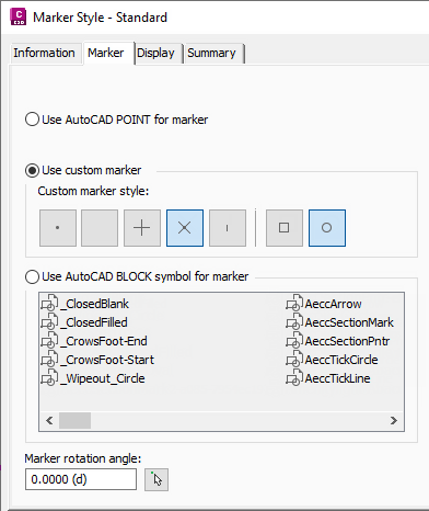
- Crossing AutoCAD objects, multi-view blocks, feature lines, and survey figures use marker styles. Marker styles are multipurpose styles and can be found in the General Multipurpose Styles Marker Styles collection on the Settings tab in Toolspace.
Marker styles can be set up to use AutoCAD points, custom marker symbols, or blocks.
3D solids can also use <Section> as the crossing marker style. By selecting the <Section> style, the solid is drawn so that it represents the actual position of where the sample line crosses the solid.
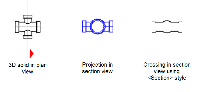 Note: The color of a 3D solid crossing that uses the <Section> option is now controlled by the 3D solid layer. Previously the appearance of a 3D solid crossing that used the <Section> option was controlled by the projection style associated with the solid.
 - For label styles, crossing objects use crossing label styles which can be found in the Section View Label Styles Crossing collection on the Settings tab in Toolspace.
Labeling Crossings and Projections with Property Set Data
You can add property set data to crossing and projection labels if Crossing Section Label and/or Projection Section Label have been added to the Applies To list for the property set.
To set up a property set to label crossings and projections in section view
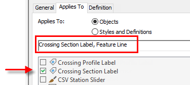
If you want to include property set data in crossing label styles, you need to select the Crossing Section Label object type in addition to the object type whose crossing location is shown in the section view.
For example, to label feature line crossings in section views with property set data, you would select Crossing Section Label and Feature Line on the Applies To tab of the Style Manager when setting up the property set definition:
You would apply this property set to the feature lines and add the relevant property set data to the crossing label style using the Text Component Editor as described in To Add Property Set Data to Labels.
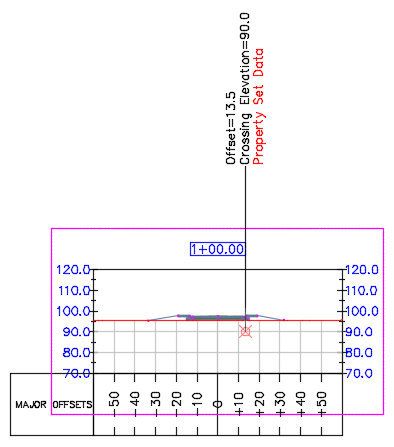
The following illustration shows an example of including property set data (in red) in a crossing label, where "property set data" represents the data you would apply to the feature line.
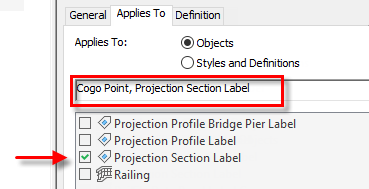
If you want to include property set data in projection label styles, you need to select the Projection Section Label object type in addition to the object type whose projection is shown in the section view.
For example, to label Autodesk Civil 3D point projections in section views with property set data, you would select Projection Section Label and Cogo Point on the Applies To tab of the Style Manager when setting up the property set definition:
You would apply this property set to the points and then add the relevant property set data to the projection label style using the Text Component Editor.
For more information about defining property sets, see About Property Sets. For more information about crossings and projections, see About Working With Projections and Crossings in Section Views.