
To create a projection style
Projection styles are used to display AutoCAD objects and multi-view blocks in section view.
- In Toolspace, on the
Settings tab, expand the General
 Multipurpose Styles collection. Right-click Projection Styles and click
New.
Multipurpose Styles collection. Right-click Projection Styles and click
New.
- In the Projection Styles dialog box, specify the name of the style and other settings as required.
- Click OK.
To control how projected AutoCAD solids are displayed in section view
- On the
Toolspace
Settings tab, expand
General
Multipurpose Styles
Projection Styles.
- Right-click a projection style and click Edit.
- On the Section tab, select AutoCAD Solids.
- Select the As Drawn option.
- Save the projection style and apply it to the AutoCAD solids you project to sections.
Note: When you project AutoCAD solids to section views, and choose to display crossings, the solid can be drawn so that it represents the actual position of where the sample line crosses the solid. To display this type of crossing for a solid, select <Section> as the crossing marker style in the
Projections and Crossings Output Display Options dialog box or on the
Projections and Crossings tab of the Section View Properties dialog box.
You can control the appearance of 3D solid crossings that use the <Section> style option by modifying the properties of the 3D solid layer.
To edit the style of a projected object
- In the drawing window, in a section view, select the object whose style you want to change.
- Click
Find.
- In the dialog box, make changes as required.
Note: To edit the style of a crossing, use the
Projections and Crossings tab in the
Section View Properties dialog box.
To create a marker style
Marker styles are used to mark the locations of crossings in section view.
- In Toolspace, on the
Settings tab, expand the General Multipurpose Styles collection. Right-click Marker Styles and click
New.
- In the Marker Styles dialog box, specify the name of the style and other settings as required.
- Click OK.
To create a projection label style
Projection label styles are used to label projected objects in section view.
- In Toolspace, on the
Settings tab, expand the Section View Label Styles collection. Right-click Projection Styles and click
New.
- In the Label Style Composer dialog box, specify the name of the style and other settings as required.
- Click OK.
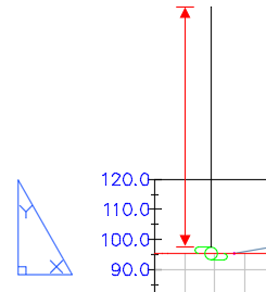
Projection and crossing labels use the following Default Projection Label Settings in the Edit Feature Settings - Section View dialog box:
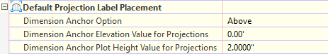
The Dimension Anchor Plot Height Value for Projections option controls the leader line height when the Dimension option is used for either the start or end anchor point in the projection or crossing label style. This value is in paper space units.
To create a crossing label style
Crossing label styles are used to label crossing objects in section view.
- In Toolspace, on the
Settings tab, expand the Section View Label Styles collection. Right-click Crossing Styles and click
New.
- In the Label Style Composer dialog box, specify the name of the style and other settings as required.
- Click OK.