
You can project objects to multiple section views by specifying projection rules and selection filters for the objects.
Using the projection rules, the objects of a specified type within an area before and after the sample lines are projected.
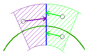
Objects of the type selected are projected if they fall within the area specified in the Projection Rules, and if they meet the filter criteria that is specified in the Source Layers and Source Display columns.
Linear objects such as feature lines, survey figures, and 3D polylines are projected only when they intersect a sample line for a given section view. The projection rules do not apply to these objects.
Projection Rule: By Percentage Option
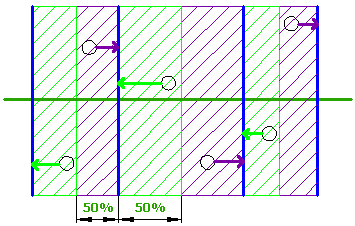
The By Percentage option is useful when the sample lines are not evenly distributed along the alignment. For example, in the following illustration, using a percentage of 50 will encompass all the area between sample lines even though they are different distances apart.
Projection Rule: By Distance Option
The By Distance option is useful when the sample lines are distributed uniformly or if you only want to include objects that are an absolute distance away from the sample lines.
The following illustration shows how objects within a specified distance of 25’ before and after the sample lines are projected.

If an object’s insertion point is within the area, then it is projected even if part of the object extends beyond the region, as shown by the object in the lower-left corner of the illustration.
Projection Rules for Non-Perpendicular and Non-Radial Sample Lines
The Project Objects To Multiple Section Views command assumes the following:
- Sample lines (solid blue lines) are considered to be either perpendicular or radial to the alignment (dotted blue lines).
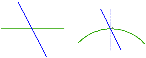
- The locations of the objects to be projected are considered to be relative to the alignment stations (1 and 2 in the following illustration).
In cases where you have non-perpendicular or non-radial sample lines, an object that appears to be “before” or “after” a sample line can actually be in the opposite position because of the way the object’s station is determined relative to the alignment.
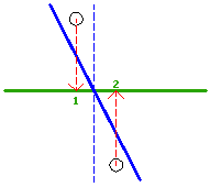
The following illustration shows how this is determined. The station of object 1 is determined to be before the location where the sample line crosses the alignment (4), so the projection rules for “before” are used for it, even though the object itself appears to be after the skewed sample line (3).
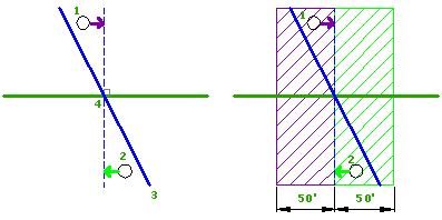
The opposite is true for object 2. It is determined to be after the sample line according to its station, so the rules for “after” are applied to it. Since both objects fall into either a “before” or “after” region, they are both projected.
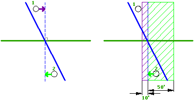
The following illustration shows how the projection results are affected by a smaller “before” region. Because the station of object 1 now falls outside of the region, object 1 is not projected.
Object Type Selection and Filtering by Layer, Style, and Point Group
Use the options in the lower part of the Project Objects to Multiple Section Views dialog box to select the types of objects to project and to specify options for filtering the selection.
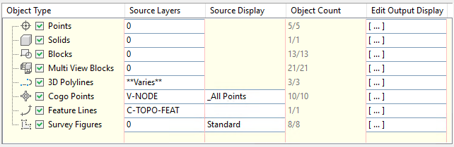
- Object Type: Specifies which object types to project. Select the check boxes in this column to project objects of that type.
Note: If some objects that you select are not within the swath width of the sample lines, they are included in the Object Count but they are not projected.
- Source Layers: Filters the selection of objects by layer. Click in a cell to open the Select Entities By Layer dialog box.
- Source Display: Filters the selection of Autodesk Civil 3D feature lines and survey figures by style and the selection of COGO points by point group. Click in a cell to open the Select Entities By Style dialog box or the Select Cogo Points By Point Group dialog box.
- Object Count: Displays the number of objects selected based on the
Source Layers and
Source Display filter settings.
Note: The Object Count value does not update based on changes to the By Percentage or By Distance settings in the upper part of the dialog box.
- Edit Output Display: Specifies whether to draw crossings and projections, and associated styles and labels, for each object in the object type, and specifies the elevation option for each object. Click in the cell to open the Projection and Crossing Output Display Options dialog box.