
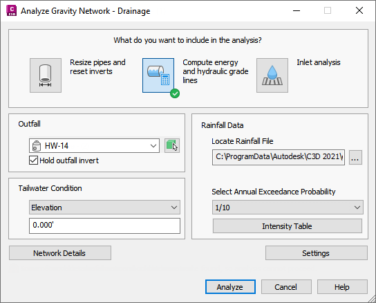
You can use the Analyze Gravity Network command to resize pipes and reset inverts and to compute the energy and hydraulic grade lines according to HEC-22 standards.
You can use this utility to:
- Analyze a pipe network using appropriate rainfall data
- Review results graphically and in a .csv file
- Apply the results to the pipe network
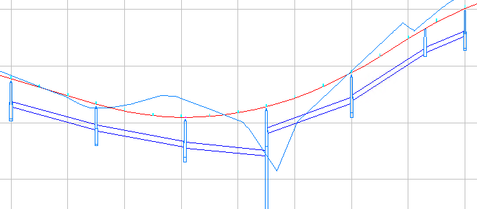
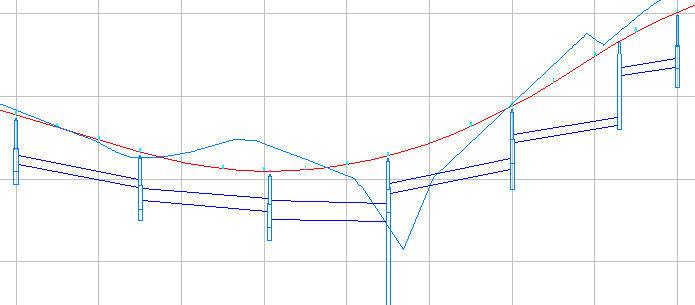
Following is a before and after example of analysis results for a pipe network shown in profile view.
| Pipe network before resizing | Pipe network after resizing |
|---|---|
|
|
|
There are three analysis types you can select: Resize Pipes and Reset Inverts, Compute Energy and Hydraulic Grade Lines, and Inlet Analysis.
- Resize Pipes and Reset Inverts: Analyzes the flow through the pipes, and then resizes the pipes and resets inverts to accommodate the flow. You have the option to apply these results to the pipe network from the
Results page of the dialog box. Applying the results of the analysis will update the pipe sizes and invert elevations according to the calculated results, and will apply all of the calculated properties to the pipe network.
Note: This option does not calculate hydraulic properties (EGL and HGL). To calculate hydraulic properties, select the Compute Energy and Hydraulic Grade Lines analysis type.
- Compute Energy and Hydraulic Grade Lines: Calculates the energy and hydraulic grade lines, and then reports whether each line in the system is in a normal state, surcharged, or flooded. You can display a graphical preview of the results (if a profile view is present in the drawing). You have the option to apply these results to the pipe network from the Results page of the dialog box. Applying the results of the analysis will apply the calculated energy and hydraulic grade values to the affected parts in the pipe network.
- Inlet Analysis: Analyzes the capacity of the inlets and reports the flow, depth, and spread at each inlet on the Results page of the dialog box.
The calculations are based on the Urban Drainage Design Manual Third Edition, Hydraulic Engineering Circular No. 22 (HEC-22), published by the U.S. Department of Transportation Federal Highway Administration.
- The Compute Energy and Hydraulic Grade Lines analysis follows the procedure outlined in Section 7.5, "Energy Grade Line Evaluation Procedure."
- The Inlet Analysis follows the procedure outlined in Chapter 4, "Pavement Drainage."
Workflow Prerequisites
Some prerequisites are required before doing an analysis, depending on the type of analysis you want to do.
- Create roadway geometry. To perform an inlet analysis with the Analyze Gravity Network command you will need to be able to specify the cross slope of the lane, longitudinal slope, gutter width, and cross slope of the gutter for each inlet.
- Create the pipe network including inlets, pipes, manholes, and an outfall location. If the network has been changed and you are no longer sure if the slope, cover, and other network rules are still met, run the
Apply Rules command on each structure and pipe in the pipe network before running the Analyze Gravity Network command.
- Inlets are typically created in
Autodesk Civil 3D as junction structures with an Inlet Location property of On Grade or On Sag and a Structure Type of Grate Inlet, Curb Inlet, or Combination.
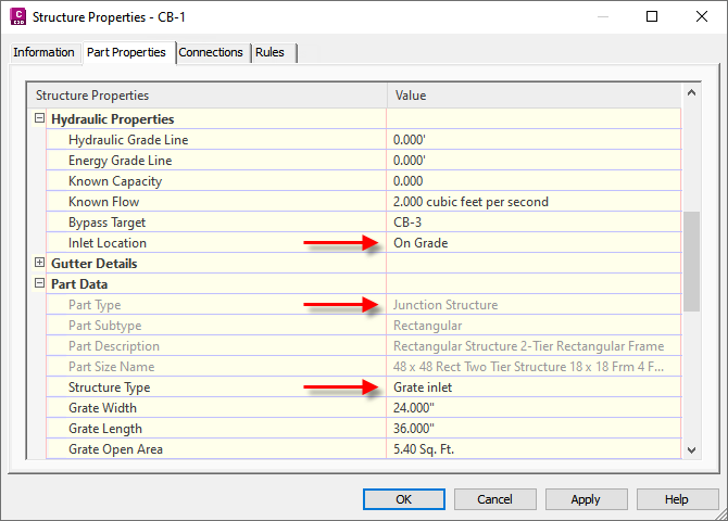
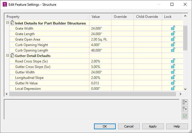
You can use the Gutter Details section of the Structure Properties dialog box to define properties of the roadway area around the inlet. These properties are used by the Analyze Gravity Network command for inlet analysis calculations.
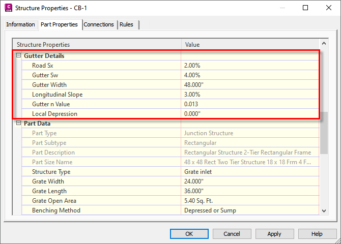 Note: You can specify Gutter Detail Default values in the Edit Feature Settings - Structure dialog box. The defaults are applied to structures when you create new pipe networks.
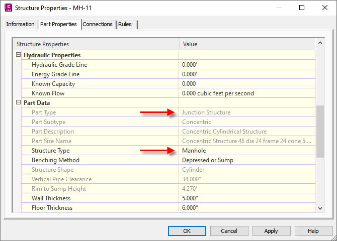
 - Manholes are typically created as junction structures and a Structure Type of Manhole.
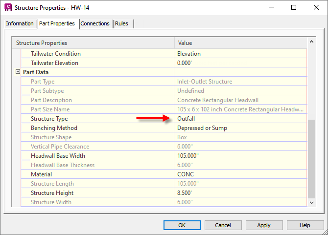
- An outfall structure is required which will be specified during the pipe sizing process. The following part types can be selected as the outfall part:
- Structures which have one or more pipes flowing into them, but do not have any pipes flowing away from them.
-
Structures which have Outfall specified as the Structure Type on the
Part Properties tab of the Structure Properties dialog box.
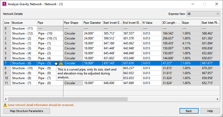
- Curved pipes can be analyzed, and they maintain their curvature after results are applied. The analysis may update their size and start/end elevations.
- Any non-circular pipe is handled as a circular pipe during the analysis. The inner width is used as the diameter.
- The pipe network does not need to be associated with a reference surface. However, when there is a reference surface, the surface elevation will be used to calculate the cover value. If there is no reference surface, the structure rim will be used to calculate the cover value.
- The minimum cover specified in the Settings applies to all pipes except the most downstream pipe (connected to the outfall structure). This may result in the outfall structure and its connected pipe appearing above ground when the surface slope is steeper than the slope of the most downstream pipe, unless you select the Hold Outfall Invert check box on the General page. The Hold Outfall Invert setting will hold the elevation at the outfall, and the elevations of the rest of the pipe network may be lowered based on the calculated pipe slopes.
- If the selected pipe network is data-referenced, the energy and hydraulic grade lines can be computed, but analysis results cannot be applied to the pipe network.
- Optionally add the pipe network to a profile view in the drawing. This enables you to preview the changes to the pipe network from the Results page of the dialog box using the Profile option.
- Inlets are typically created in
Autodesk Civil 3D as junction structures with an Inlet Location property of On Grade or On Sag and a Structure Type of Grate Inlet, Curb Inlet, or Combination.
- Create catchments (from a surface or from objects) that are associated with the inlets. When you create catchments, the runoff coefficient is specified manually and the area and the time of concentration (Tc) are computed as properties of the catchment. These values are used in the pipe sizing process. However, if the Tc that was calculated for a catchment is less than the minimum specified in the Settings, the value from the settings will be used instead.
- Determine if there is additional flow that will enter the system. Known flow can also be specified for an inlet if a catchment does not exist for that inlet.
- Prepare or obtain a rainfall data file for the location. This can exist in the form of a NOAA .csv or X-Degree .csv file or a Hydraflow .idf file. Sample rainfall files are installed to C:\ProgramData\Autodesk\C3D 2026\enu\HHApps\IDF.
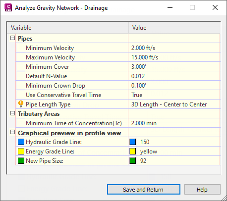
Specifying Default Settings
Settings that must be specified manually for the tributary areas and pipes, or which are used as values in the analysis calculations, can be pre-established as defaults on the Settings page. Click the Settings button on the General page to open this dialog box.
Default settings for structures can be specified in the Edit Feature Settings - Structure dialog box.
Parameter Mapping for Parts Created with Part Builder
You can map the parameters of parts created with Part Builder to parameters that are required for the Analyze Gravity Network command.
By mapping the parameters and applying them to the structures in existing pipe networks, you will not need to manually specify the values when you are using the Analyze Gravity Network command.
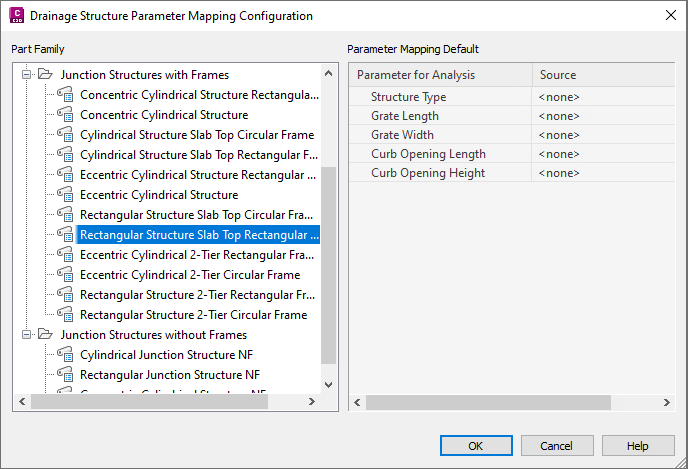
For more information, see To Map Drainage Structure Parameters for Gravity Network Analysis.
Network Details Information
Use the Network Details page of the Analyze Gravity Network dialog box to review and change the network detail information that is relevant to the selected analysis types.
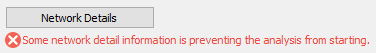
If the analysis type you select cannot be performed, an error message is displayed below the Network Details button on the General page of the Analyze Gravity Network dialog box.
If some of the network detail information should be reviewed, a warning message is displayed below the Network Details button on the General page.
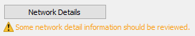
Click the Network Details button to open the Network Details page where you can review errors and warnings and change the network detail settings.
For more information, see Network Details Page (Analyze Gravity Network Dialog Box).
Analysis Results
When you click the Analyze button in the Analyze Gravity Network dialog box, the Results page is displayed.
Visual cues and tooltips are displayed to indicate the analysis results.
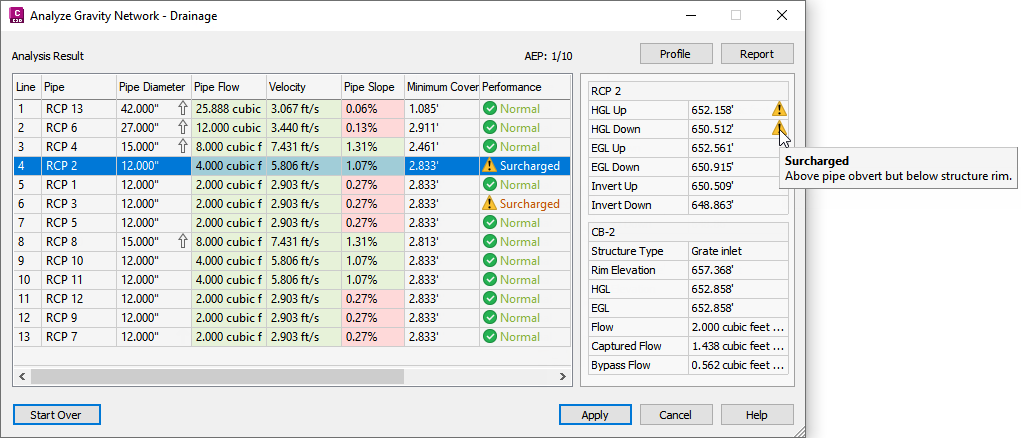
When you select a row in the results table, the right panel displays detailed information about the pipe and structure in the selected line.
For more information, see Results Page (Analyze Gravity Network Dialog Box).
Pipe Network Part Replacement
For the Resize Pipes and Reset Inverts analysis type, the Analyze Gravity Network command checks the current part catalog for replacement parts. If a required part size is in the catalog but does not exist in the current part list, then it is added to the current part list after the parts are replaced.
If the analysis determines that a different part size is required, that size will be queried from the original family of the pipe, and if the required size does not exist in that family, other part families that are used in the pipe network will be queried from. This may result in the material of one pipe being changed for a different material (but only if the other material is already used in the pipe network).
| If... | and if... | then... |
|---|---|---|
| the original part is an 18 inch concrete pipe and the analysis determines that a 12 inch pipe can be used | a 12 inch concrete pipe exists in the part catalog | the 12 inch concrete pipe will be used |
| the original part is an 12 inch concrete pipe and the analysis determines that a 10 inch pipe can be used | a 10 inch concrete pipe does not exist in the part catalog | then other part families that are used in the pipe network will be queried from for a 10 inch pipe
Note: Notifications are not made when the material of a pipe is changed for a different material in order to match the recommended size. To review the pipe materials, you can output a pipe report or create a table in the drawing that includes a column to show the pipe material.
|
Post-Sizing Refinements
- After applying the results to a pipe network to which pipe rules have been applied, it is recommended that you review the pipes on the Prospector tab in Toolspace to see if the rules have been broken.
- The outfall structure location and/or elevation may need to be modified to meet the desired cover value.