
You can map the parameters of parts created with Part Builder to parameters that are required for the Analyze Gravity Network command.
By mapping the parameters and applying them to the structures in existing pipe networks, you will not need to manually specify the values when you are using the Analyze Gravity Network command.
To map drainage structure parameters and apply the mapping to existing pipe networks
Use the following method to map drainage structure parameters for the current pipe network catalog and apply the parameter mapping to structures in existing pipe networks.
- On the
Home tab click
Create Design panel
 drop-down button
Map Drainage Structure Parameters
drop-down button
Map Drainage Structure Parameters
 .
.
- In the Map Drainage Structure Parameters dialog box, specify whether you want to apply the parameter mapping to all fields of the parts in existing pipe networks, or whether you want to apply the parameter mapping to empty fields only.
- Click Mapping Configuration to display the Drainage Structure Parameter Mapping Configuration dialog box.
- Specify the mapping configuration for each part that needs to be mapped.
- Click OK twice to apply the mapping configuration to the parts in the drawing.
To map drainage structure parameters in a parts list
Use the following method to map drainage structure parameters in a parts list.
- In Toolspace, on the Settings tab, expand the Pipe Network collection, and then expand the Parts Lists collection.
- Right-click the desired parts list and click Edit Parts List. The Network Parts List dialog box is displayed.
- Click the Structures tab.
- Expand the parts list to see the part families that are included in the list.
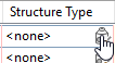
- In the Structure Type column, click the structure icon to display the
Drainage Structure Parameter Mapping Configuration dialog box.
- Specify the mapping configuration for the part.
- Click OK.
To map drainage structure parameters during pipe network analysis
Use the following method to map drainage structure parameters while using the Analyze Gravity Network command and to apply the parameter mapping to structures in existing pipe networks.
- Click
tab panel
Find.
- Select the pipe network you want to analyze. You can select the network in the drawing or press Enter and select the pipe network from the Select Pipe Network dialog box.
After you select the pipe network, the Analyze Gravity Network dialog box is displayed.
- Click Network Details to open the Network Details page.
- Click Map Structure Parameters.
- In the Map Drainage Structure Parameters dialog box, specify whether you want to apply the parameter mapping to all fields of the parts in existing pipe networks, or whether you want to apply the parameter mapping to empty fields only.
- Click Mapping Configuration to display the Drainage Structure Parameter Mapping Configuration dialog box.
- Specify the mapping configuration for each part that needs to be mapped.
- Click OK twice to apply the mapping configuration to the parts in the drawing.
To specify default parameter mapping settings
Use the following method to set up default parameter mapping settings.
- In Toolspace, on the Settings tab, right-click the Pipe Network collection. Click Edit Feature Settings to open the Edit Feature Settings - Pipe Network dialog box.
- Expand the
 Catalog Parameter Mapping property group.
- In the
Structure Type and Dimension Mappings field, click
 to display the
Drainage Structure Parameter Mapping Configuration dialog box.
to display the
Drainage Structure Parameter Mapping Configuration dialog box.
- Specify the mapping configuration for each part that needs to be mapped.
- Click OK twice.