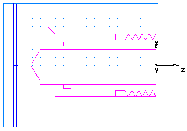
This shows you how to create the turning features.
- Select View tab > Appearance panel > Line Display menu > Turning 2D View to switch to a simplified 2D representation of the part.
- Create a Turn feature.
- Select Home tab > Part Program panel > Features.
- In Turn/Mill documents, the New Feature wizard asks you which type of feature you want to create. Select the Turning option, and click Next.
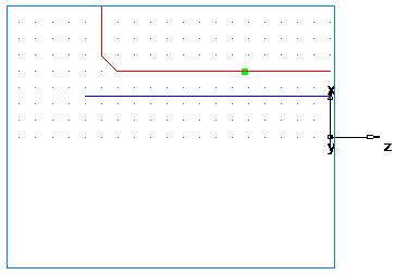
- Select Turn in the From Curve section, and click Next.
- In the
Curve field select
turn from the list.
Click the Pick Curve
 button to select the curve graphically. The dialog minimizes to reveal the graphics window beneath.
Click the curve you named turn earlier.
In this case, two objects are available for selection: a line and a curve. Whenever your selection must be clarified, FeatureCAM opens the Select dialog.
In the Select dialog, select turn, and click OK.
- From the
Finish menu button, select the
Finish and Create More option to continue creating features.
- Create a Face feature:
- In the New Feature wizard, select the Turning option, and click Next.
- In the From Dimensions frame, select Face, and click Next.
- On the
Dimensions page:
Enter a Thickness of 0.0625 (1.5 mm).
Enter an Outer Diameter of 4 (100 mm).
Enter an Inner Diameter of 0.
Click Next.
- Click Finish and Create More.
- Create a Hole feature.
- In the New Feature wizard, select the Turning option, and click Next.
- In the From Dimensions frame, select Hole, and click Next.
- On the
Dimensions page:
Enter a Depth of 3.75 (94 mm).
Enter a Diameter of 1.0 (24 mm).
Click Next.
- On the Location page enter a Z of 0.
- Click
Finish and Create More.
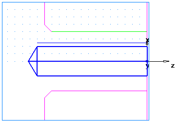
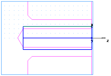
- Create a Bore feature by using the same process you used to create the Turn feature. Use the curve named
Bore.
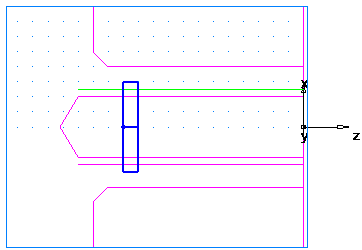
- Create a Groove feature.
- In the New Feature wizard, select the Turning option, and click Next.
- In the From Dimensions frame select Groove, and click Next.
- On the
Dimensions page:
Select a Location of ID.
Select an Orientation of X axis.
Enter a Diameter of 1.25 (31 mm).
Enter a Depth of 0.125 (3 mm).
Enter a Width of 0.25 (6 mm).
Leave the other settings at 0.
Click Next.
- On the Location page enter a Z of -3 (-75 mm).
- Click
Finish and Create More.
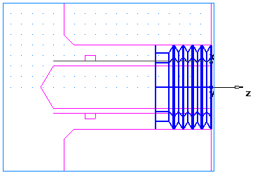
- Create a Thread feature.
- In the New Feature wizard, select the Turning option, and click Next.
- In the From Dimensions frame, select Thread, and click Next.
- On the
Dimension page:
Select Get the thread dimensions from a standard thread.
Select OD.
In the Designation field select the 2.0000- 4.5 UNC (M50-15 for metric).
Click Next.
- On the
Dimensions
page:
Select a Thread of Right hand.
Enter a Thread Length of 1.0 (24 mm).
Click Next.
- Click
Finish and Create More.
- Create a Cutoff feature.
- In the New Feature wizard, select the Turning option, and click Next.
- In the From Dimensions frame select Cutoff, and click Next.
- On the
Dimensions page:
Enter a Diameter of 4 (100 mm).
Enter an Inner Diameter of 0.
Enter a Width of 0.122 (3 mm).
Click Next.
- On the Location page enter a Z of –4.5 (–112 mm).
- Click
Finish.