
This shows you how to design your part.
- Draw two lines:
- Click Construct tab > Geometry panel > Line > 2 Points.
- The Feature/Geometry Edit bar is displayed.

- In the Feature/Geometry Edit bar:
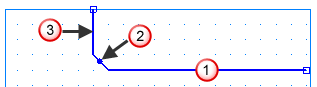
For point 1, enter an XYZ 1 of X 2 (50 mm), Y 0, Z -3.5 (-88 mm).
For point 2, enter an XYZ 2 of X 1 (25 mm), Y 0, Z -3.5 (-88 mm).
Press Enter. This draws a line in the graphics window.
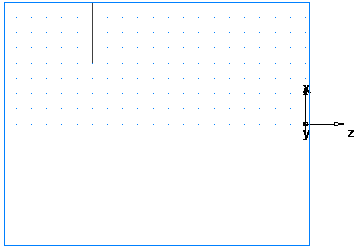
- Create a second line:
For point 1 enter an XYZ 1 of X 1 (25 mm), Y 0, Z -3.5 (-88 mm).
For point 2 enter an XYZ 2 of X 1 (25 mm), Y 0, Z 0.
Press Enter to create a second line.
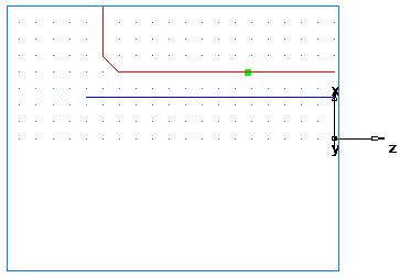
- Click Construct tab > Geometry panel > Fillet > Chamfer.
- In the Feature/Geometry Edit bar, enter:
A width of 0.25 (6 mm).
A height of 0.25 (6 mm).
- Position your mouse pointer close to the chamfer location. The chamfer snaps into place.
- Click to place the chamfer on your drawing. The chamfer automatically trims your lines.
- Create a chamfer to trim your lines.
- Click Construct tab > Geometry panel > Fillet > Chamfer.
- In the Feature/Geometry Edit bar, enter:
A width of 0.25 (6 mm).
A height of 0.25 (6 mm).
- Position your mouse pointer close to the chamfer location. The chamfer snaps into place.
- Click to place the chamfer on your drawing. The chamfer automatically trims your lines.
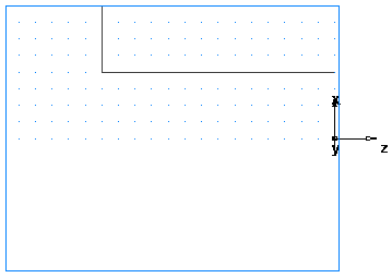
- To turn the part you need to convert these three individual lines into a single curve (chain the curve).
- Select Home tab > Create panel > Chaining > Pick Pieces.
- In the graphics window, click locations
 ,
,
 , and
, and
 . Each line segment changes color when selected.
- In the Feature/Geometry Edit bar, name the curve turn, and press Enter.
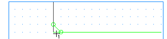
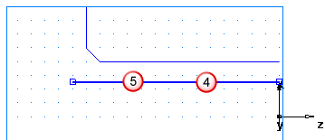
- Create third line which you will use to create a Bore feature.
- Click Construct tab > Geometry panel > Line > 2 Points.
- In the Feature/Geometry Edit bar:
For point 1 enter an XYZ 1 of X 0.625 (16 mm), Y 0, Z 0.
For point 2 enter an XYZ 2 of X 0.625 (16 mm), Y 0, Z -3.75 (-94 mm).
- Press Enter.
- To chain the bore curve:
- Select Home tab > Create panel > Chaining > Pick Pieces.
- In the graphics window, click locations
4 and
5
(you select the same line twice).
- In the Feature/Geometry Edit bar, name the curve bore, and press Enter.