- Click View tab > Views panel > ISO menu > ISO 1.
- Control how the part is displayed using the Display Options.
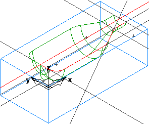
- Click File > Options > Display > Wireframe page and select
Show surface boundaries only, and click
OK.
This displays the surfaces as only their outer boundaries and trimmed loops. No additional lines are drawn in the interior of the surface. This makes the display of larger models much faster.
- Click File > Options > Display > Wireframe page and deselect
Show surface boundaries only, and click
OK.
This displays the surfaces with lines in the interior of the surface. This aids visualization, but for large models, it makes the display of the part slower.
- Click File > Options > Display > Wireframe page and enter a
Surface fineness
Wireframe of
20, and click
OK.
This displays the surfaces with more lines. Decreasing the value of Surface Fineness improves the display quality but slows down the graphics.
- Click File > Options > Display > Wireframe page and select
Show surface boundaries only, and click
OK.
- Click View tab > Visibility panel > Hide menu > Hide All Geometry.
- Click View tab > Visibility panel > Show menu > Show All Surfaces.
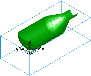
- Click View tab > Appearance panel > Shading menu > Shade Surfaces.