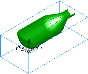
This shows you how to design your part.
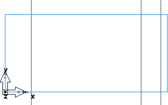
- Create three vertical lines:
- Click Construct tab > Geometry panel > Line menu > 2 Points.
The Feature/Geometry Edit bar is displayed.

- In the Feature/Geometry Edit bar, enter an XYZ of X 1, Z 0, and press Enter.
- Create a second line by entering an XYZ of X 5.25, Z 0, and press Enter.
- Create a third line by entering an
XYZ of
X
6,
Z
0, and press
Enter.
- Click Construct tab > Geometry panel > Line menu > 2 Points.
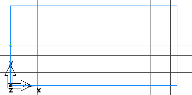
- Create three horizontal lines:
- Click Construct tab > Geometry panel > Line menu > Horizontal.
- Enter an XYZ of Y 0.5, Z 0, and press Enter.
- Create a second line by entering an XYZ of Y 1.125, Z 0, and press Enter.
- Create a third line by entering an
XYZ of
Y
1.5,
Z
0, and press
Enter.
- Create a through line:
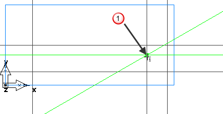
- Click Construct tab > Geometry panel > Line menu > Point, Angle.
- In the Feature/Geometry Edit bar, enter an angle A of 30.
- In the graphics window, click at the intersection between the second horizontal and second vertical lines, at point
 , to create a through line.
- Create arcs.
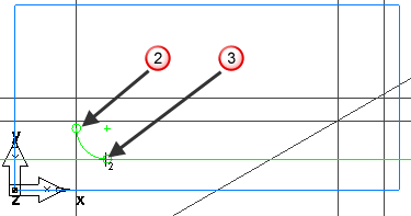
- Click Construct tab > Geometry panel > Arc menu > 2 Points, Radius.
- In the Feature/Geometry Edit bar, enter a radius
R of
0.5, and click the vertical line around point
 and the horizontal line around point
 .
.
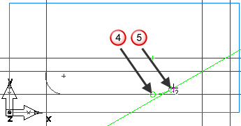
- Create the second arc:
In the Feature/Geometry Edit bar, enter a radius R of 1.0, and click the horizontal line around point
 and the through line around point
 .
.
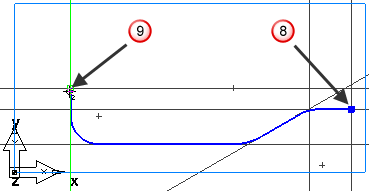
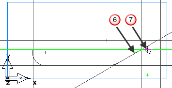
- Create the third arc by clicking the through line around point
 and the horizontal line around point
 .
.
- To mill the part you need to chain the curves.
- Select Home tab > Create panel > Chaining > Pick Pieces.
- Click at the intersection of the vertical and horizontal line at point
 and at the intersection of the vertical and horizontal line at point
 .
.