
The
Op List
tab in the
Results window shows all of the operations needed to machine the features. A yellow warning
 sign next to an operation indicates a potential problem with that operation. In this case, if you see any warnings ignore them.
You can control the automatic ordering of operations by using either rules or operation templates. The turning tutorial looks at operation templates.
- Select the Automatic Ordering option on the Op List tab. This ensures the automatic ordering rules are applied to the operations.
- Change the automatic ordering to group together the operations which use the same tool.
- Click the
Ordering options
 button.
- In the Automatic Ordering Options dialog, select Minimize tool changes, deselect everything else, and click OK.
- Click the
Ordering options
- Simulate the part.
- Click Home tab > Simulation panel > Sim mode > 3D to change the simulation type.
- Click
Play
 on the Simulation toolbar to start the simulation.
Notice that the simulation first performs all the spot-drills, then the drills, and then the rough and finish milling for the pockets.
- Click
Stop
 to end the simulation.
- Change the automatic ordering to move the finish operations to the end of the list.
- Click the
Ordering options
button.
- In the
Automatic Ordering Options dialog, select
Do finish cuts last, deselect everything else, and click
OK.
This changes the order of operations in the Operation List.
- Click
Play
on the Simulation toolbar to start the simulation.
The finish cuts for the two pockets are now cut last.
- Click
Stop
to end the simulation.
- Click the
Ordering options
- Simulate the part.
- Click
Play
on the Simulation toolbar to start the simulation.
The finish cuts for the two pockets are now cut last.
- Click
Stop
to end the simulation.
- Click
Play
- Change the automatic ordering to match the order of the features in the
Part View panel.
- Click the
Ordering Options
button.
- Deselect everything, and click OK.
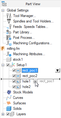
- Open the Part View panel by clicking Part View on the left of the Graphics window. The tree view contains all the setups and features you have created.
- Click the
rect_pock2 item in the
Setup1 node, and drag it up above
hole2.
- Click
Play
on the Simulation toolbar.
The second pocket is cut as the second feature.
- Click
Stop
to end the simulation.
- Click the
Ordering Options
- Simulate the part.
- Click
Play
on the Simulation toolbar.
The second pocket is cut as the second feature.
- Click
Stop
to end the simulation.
- Click
Play