
Use this menu option to check that all profile elements in CAM mode have corresponding geometric elements in CAD mode.
When the CAD/CAM Link option is selected, the CAD/CAM Switch icons change to include a link:

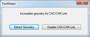
When switching from CAM mode to CAD mode, PartMaker checks if all profile elements in CAM mode have corresponding geometric elements in CAD mode. If any geometric elements are missing, PartMaker displays a message allowing you to extract geometry from the profile elements:
While in CAD mode, you can modify or/and transform geometric elements. PartMaker allows you to insert one geometric element between any two elements, for example a fillet or chamfer.
You cannot delete linked geometric elements and PartMaker ignores any gaps between adjacent geometric elements.
After switching from CAD mode back to CAM mode, PartMaker automatically applies the changes made in CAD mode to the corresponding profile elements in CAM mode.
Example of using the CAD/CAM Link menu option
- The original profile element displayed in CAM mode:

- You switch from CAM mode to CAD mode. The CAD geometry is as follows:
- You insert fillets into the CAD geometry:

- You switch from CAD mode to CAM mode.
PartMaker automatically applies the changes you made in CAD Mode to the corresponding profile element in CAM mode: