
Contour Flange Dialog - Shape Tab
Access
Ribbon: Sheet Metal tab  Create panel Contour Flange
Shape tab
Profile
Select an unconsumed sketch with an open profile that defines the shape of your contour flange.
Solids
If there are multiple bodies in the part file, click the Solids selector to choose the participating body.
Join 
Adds the volume created by the contour flange to another feature or body.
New Solid 
Creates a solid body. If the contour flange is the first solid feature in a part file, this selection is the default. Select to create a body in a part file with existing solid bodies. Each body is an independent collection of features, separate from other bodies. A body can share features with other bodies.
Edges
Edge 
Select one or more individual edges to which you apply the contour flange.
Loop 
Select an edge loop, and then apply the flange to all edges of the selected loop.
Offset
Flip Side  or
or 
When active, a click on it flips the material thickness to the opposite side of the selected profile.
Both Sides 
Creates the material thickness using the selected profile as the mid-plane of the new flange.
Sheet Metal Rule
Select the Follow Defaults checkbox to link the material thickness and rules to the Default setting. Clear the Follow Defaults checkbox and click the drop-list to specify a unique material thickness and rules from the predefined list.
Bend Radius
Defines the radius of the bend between the flange and the face containing the selected edges. The value defaults to the system parameter BendRadius that the Sheet Metal Styles dialog box defines. You can enter numeric entries, formulas, parameters, or measured values.
Bend Extension
See the Bend extension reference to review the material on Bend Extension that is common to: Bend, Face, and Contour Flange features.
Width Extents
Edge 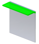
Creates a contour flange the full length of the selected face edge.
Width 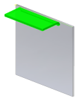
Creates a contour flange of a specified width at a specified offset from a single selected vertex, work point, work plane, or planar face on the edge of an existing face. You can specify that the flange is a specific width centered on the midpoint of the selected edge.
Offset 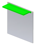
Creates a contour flange offset from two selected vertices, work points, work planes or planar faces on the edge of an existing face.
From To 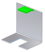
Creates a contour flange with a width that you define by selecting existing part geometry (vertices, work points, work planes, or planar faces) that defines the flange from and to extents.
Distance 
Creates a contour flange with a width that you define by a single distance value and a direction from the sketch plane.