A water supply system has many valves of varying types and functions.
Valves in a water supply system can be classified in four main groups:
- section valves: placed at pipe section ends, normally open and used only for isolation of the pipe when necessary. These may be modelled individually (as Control Valves), but a more usual policy is to ignore them in normal situations and use the Pipe Closed option on the Pipe Closed Profile page to model closing of the valve in an emergency.
- float valves (FLV): prevent overspilling from reservoirs and water towers
- non-return valves (NRV): for instance, check valves: prevent backflow
- control valves: regulate flow and/or pressure in the system or part of it
For further information on valve control see Valve Control.
Valve construction types
The following valve construction types are available for selection in InfoWorks WS Pro:
- Ball valve: Consists of a ball with a hole through it. The valve allows straight through flow when in the open position and shuts off flow when the ball is rotated by 90 degrees.
- Butterfly valve: Consists of a circular disc or vane, which rotates on a shaft at right angles to the direction of flow in the pipe. These valves are used for flow regulation. Not widely used in distribution mains as they cause an obstruction in the pipe but are more economical for larger pipes than Gate Valves.
- Gate valve: Consists of a flat face, vertical disc or gate that slides through the valve perpendicular to the direction of flow. Gate valves are widely used in water supply systems to isolate lengths of pipeline, pumps and other devices.
- Needle valve: Consists of an orifice that is the seat for a rod with a slender, tapered point. Flow through the valve turns 90 degrees, the size of the orifice being changed by lowering the rod to restrict or block flow. Used solely for flow and/or pressure control, these valves are expensive and are generally used where accurate regulation of flow at low flow rates is required.
- Plug valve: Consists of a cylindrical or tapered plug with a hole in the centre. The valve allows straight through flow when in the open position and shuts off flow when the ball is rotated by 90 degrees.
Different valve types
Valve characteristics
InfoWorks WS Pro contains a number of built in curves for typical valves, which can be viewed by right-clicking the valve curve page in the links grid.
Valve characteristics
InfoWorks WS Pro uses the built-in curves to calculate valve minor losses related to the percentage opening of the valve, specified on the Valve Control page of the Valve property sheet.
Local loss coefficient

| Opening (%) | Closure (%) | Default (Plug) | Ball | Butterfly | Gate Needle | ||
|---|---|---|---|---|---|---|---|
|
1 |
0 |
100 |
1e6 |
1e6 |
1e6 |
1e6 |
1e6 |
|
2 |
1 |
99 |
1e5 |
500000 |
400000 |
10000 |
5000 |
|
3 |
2 |
98 |
30000 |
180000 |
95000 |
3000 |
1500 |
|
4 |
3 |
97 |
11500 |
70000 |
32000 |
1200 |
575 |
|
5 |
5 |
95 |
4900 |
30000 |
15000 |
420 |
250 |
|
6 |
10 |
90 |
1740 |
13000 |
5000 |
150 |
97 |
|
7 |
15 |
85 |
800 |
10000 |
900 |
60 |
48 |
|
8 |
20 |
80 |
380 |
2250 |
400 |
35 |
25 |
|
9 |
25 |
75 |
190 |
600 |
190 |
19 |
18 |
|
10 |
30 |
70 |
103 |
235 |
102 |
10 |
13 |
|
11 |
35 |
65 |
58 |
120 |
60 |
6 |
10 |
|
12 |
40 |
60 |
34.0 |
66 |
34 |
4.6 |
8.4 |
|
13 |
45 |
55 |
21.0 |
40 |
20 |
3.0 |
7 |
|
14 |
50 |
50 |
13.3 |
22.5 |
12.5 |
2.06 |
5.7 |
|
15 |
55 |
45 |
9.0 |
12. |
8.0 |
1.4 |
5 |
|
16 |
60 |
40 |
6.3 |
8.0 |
4.65 |
0.98 |
4.35 |
|
17 |
65 |
35 |
4.7 |
5.0 |
2.80 |
0.6 |
4 |
|
18 |
70 |
30 |
3.6 |
2.9 |
1.70 |
0.44 |
3.45 |
|
19 |
75 |
25 |
2.8 |
1.8 |
1.2 |
0.28 |
3.2 |
|
20 |
80 |
20 |
2.3 |
1.01 |
0.82 |
0.17 |
2.90 |
|
21 |
85 |
15 |
1.9 |
0.6 |
0.65 |
0.11 |
2.75 |
|
22 |
90 |
10 |
1.7 |
0.41 |
0.48 |
0.06 |
2.60 |
|
23 |
95 |
5 |
1.6 |
0.28 |
0.37 |
0.01 |
2.45 |
|
24 |
100 |
0 |
1.5 |
0.20 |
0.31 |
0.0 |
2.35 |
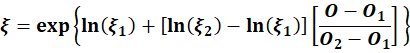
For an intermediate opening
O, where
 , a non-linear interpolation is used to determine the local loss coefficient
 , which satisfies
 .
.
The interpolation is given by:
Flow coefficient Kd =

| Opening (%) | Closure (%) | Default (Plug) | Ball | Butterfly | Gate Needle | ||
|---|---|---|---|---|---|---|---|
|
1 |
0 |
100 |
0.001 |
0.001 |
0.001 |
0.001 |
1E-6 |
|
2 |
1 |
99 |
0.003 |
0.001 |
0.002 |
0.010 |
0.014 |
|
3 |
2 |
98 |
0.006 |
0.002 |
0.003 |
0.018 |
0.026 |
|
4 |
3 |
97 |
0.009 |
0.004 |
0.006 |
0.029 |
0.042 |
|
5 |
5 |
95 |
0.014 |
0.006 |
0.008 |
0.049 |
0.063 |
|
6 |
10 |
90 |
0.024 |
0.009 |
0.014 |
0.081 |
0.101 |
|
7 |
15 |
85 |
0.035 |
0.010 |
0.033 |
0.128 |
0.143 |
|
8 |
20 |
80 |
0.051 |
0.021 |
0.050 |
0.167 |
0.196 |
|
9 |
25 |
75 |
0.072 |
0.041 |
0.072 |
0.224 |
0.229 |
|
10 |
30 |
70 |
0.098 |
0.065 |
0.099 |
0.302 |
0.267 |
|
11 |
35 |
65 |
0.130 |
0.091 |
0.128 |
0.378 |
0.302 |
|
12 |
40 |
60 |
0.169 |
0.122 |
0.169 |
0.423 |
0.326 |
|
13 |
45 |
55 |
0.213 |
0.156 |
0.218 |
0.500 |
0.354 |
|
14 |
50 |
50 |
0.264 |
0.206 |
0.272 |
0.572 |
0.386 |
|
15 |
55 |
45 |
0.316 |
0.277 |
0.333 |
0.645 |
0.408 |
|
16 |
60 |
40 |
0.370 |
0.333 |
0.421 |
0.711 |
0.432 |
|
17 |
65 |
35 |
0.419 |
0.408 |
0.513 |
0.791 |
0.447 |
|
18 |
70 |
30 |
0.466 |
0.506 |
0.609 |
0.833 |
0.474 |
|
19 |
75 |
25 |
0.513 |
0.598 |
0.674 |
0.884 |
0.488 |
|
20 |
80 |
20 |
0.550 |
0.705 |
0.741 |
0.925 |
0.506 |
|
21 |
85 |
15 |
0.587 |
0.791 |
0.778 |
0.949 |
0.516 |
|
22 |
90 |
10 |
0.609 |
0.842 |
0.822 |
0.971 |
0.527 |
|
23 |
95 |
5 |
0.620 |
0.884 |
0.854 |
0.995 |
0.538 |
|
24 |
100 |
0 |
0.632 |
0.913 |
0.874 |
1.000 |
0.546 |
Valve minor losses
The minor loss through a valve is calculated using a built-in or user-defined valve curve. The curve used depends on the construction type of the valve. These curves can be viewed in the Valve Parameters page of the Valve property sheet.
A scaling factor to be applied to the valve curve is calculated as follows:
The user specifies the Loss Coefficient for the valve when it is fully open. This value is related to the geometry of the valve and is specified by the manufacturer. (If a loss coefficient is not specified, InfoWorks WS Pro assumes a minimum value of 0.01 for the Valve Curve Loss Coefficient Multiplier).
The Valve Curve Loss Coefficient Multiplier is calculated as:
|
|
Where:
|

The Valve Curve Loss Coefficient Multiplier is then applied to the valve curve.
The valve minor loss is calculated as:
|
|
Where:
V Velocity:
where: Av nominal full open area of valve |