
Bow
The Bow shape for the part or portion of the part forms a simple curve shape.
In the following figure, there are three examples of a bowed part that is compared to the base part and a warpage tolerance. The top half of the figure is a front view, and the bottom half shows the parts as rotated. The three red bowed parts are the same. The difference between them is how they are compared to the tolerance.
The left part in green (A) is the original part, is perfectly flat, and is the desired shape. The two blue planes represent the +/- 5.0-mm tolerance. The second part from the left (B) is the part with best fit applied. With best fit, the part is in tolerance.
The third part from the left (C) has anchors in three corners. In this example, the part is in the XY-plane, so deflection in the Z-direction defines flatness for the part. The tolerance planes are +/- 5 mm from 0-Z in this case. The anchors are at 0-Z and with the anchors being in the corners, all the deflection is in one direction, the -Z-direction in this case. As the tolerance is stated +/- 5.0 mm, the part is not in tolerance. However, if the part has a geometric flatness tolerance of 10 mm, the part would be in tolerance.
The part on the right (D) is a part where three anchors are used but on one end of the part. The position of the anchors makes the part look way out of tolerance, even though all three red parts are the same. The type of anchor placement used here is not a good idea unless the locations picked relate to assembly features. For a general idea of the shape of the part, use three nodes widely spaced on the part.
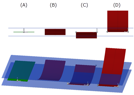
A = Original part
B = Bowed part with Best fit
C = Bowed part with anchors in 3 corners
D = Bowed part with 3 anchors on one end of the part
Blue planes represent the part tolerance