
Only tetrahedral solid elements are available currently in the software. Both linear and parabolic types are available. Solids are used to model thick structures where stress in all directions is significant and of interest.
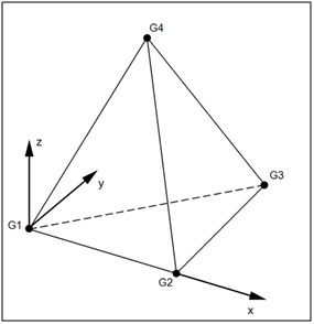
Linear
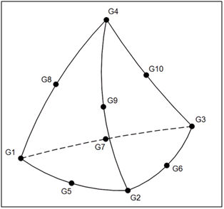
Parabolic
Elemental Geometry
Using the image of the linear solid tetrahedral element we can see that the origin of the element coordinate system is at G1. The element x-axis is defined by the vector G1 –G2. The element y-axis is orthogonal to the element x-axis and is in the G1-G2-G3 plane. The element z-axis is found using from the cross product of element x and element y.
Formulation Options
There are two forms of solid tetrahedral elements currently available in this software: linear and parabolic. Linear elements have only 4 nodes. Parabolic solid tetrahedral elements have 10 nodes. Linear elements are stiffer and parabolic elements are more flexible.
Degrees of Freedom
Solid elements do not have rotational degrees of freedom at each node. A moment or a torque applied to the face of a solid element mesh (linear or parabolic) will result in zero or null output. A force couple or rigid element must be used to apply a torque or moment to a surface that has an associated solid mesh.
Element Output
All solid element results are given in the global rectangular coordinate system. The solid elemental results are the result of averaging the Gaussian point results. The nodal results (or corner results) are extrapolated to the node using the nearby Gauss point and the shape functions of the elements (more on element theory can be found in any finite element text book).