The linearization controls, found on the right side of the Stress Linearization utility dialog, allow you to specify the first and last point to define the Stress Classification Line (SCL). You can also define the coordinate system for the local stress tensor graph.
What is a Stress Classification Line (SCL)?
- A stress classification line is a straight line that generally extends from free surface to free surface of a material. In other words, an SCL is typically drawn across the thickness of a given section of a solid. However, non-solid shell elements are also supported, and you can define the SCL in any direction, as long as it intersects elements in your model.
- Stress tensor results along the SCL are presented in a graph. The tensors are based on a local coordinate system dictated by the SCL endpoints, a third (reference) point, and the N Axis or H Axis option you choose.
Point and Axis Definition Controls
- First Point: Defines the starting point of the SCL.
- Last Point: Defines the endpoint of the SCL.
- Reference Point: Indicates the direction of the N or H axis.
These points are selected by one of three methods:
- Typing the node number into the Node field.
- Placing your cursor in the Node field and graphically selecting a point in the model display.
- Typing the coordinates of any point on the model into the X, Y, and Z fields.
Note: The SCL must intersect elements in your model, but SCL endpoints and reference points do not have to be at FEA nodes.Tip: If you select nodes graphically, the node number and the X, Y, and Z coordinate fields are populated automatically. Take note of the node numbers to conveniently duplicate the SCL definition for subsequent stress linearization calculations when using the same model mesh.
- Perpendicular Direction:
The stress values along the SCL are reported as six stress tensors based on a local coordinate system. Therefore, you need to define the three perpendicular directions on which the tensor calculations are based. These axes are named the T, N, and H. The positive T axis is defined by the direction of the SCL, First Point to Last Point. The Reference Point defines either the
N Axis or the
H Axis direction, depending on which radio button you activate.
- If the N Axis option is selected, a line perpendicular to the T axis passing through the Reference Point defines the N axis direction. The H axis is then defined as the axis perpendicular to both the T and N axes.
- If the H Axis option is selected, a line perpendicular to the T axis passing through the Reference Point defines the H axis direction. The N axis is then defined as the axis perpendicular to both the T and H axes.
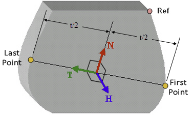
- Regardless of the option you select, the N axis is the cross product of the T and H axes, following the right-hand rule.
The figure below shows the local axis configuration if the N Axis is defined: