
This page addresses the Solver option for the Surface Contact type.
This option allows you to define Automatic Surface Contact Generation (ASCG) for the model (globally) or for specified contact regions. It allows you to override the default contact settings defined within the Analysis dialog (unlike the fully Automatic contact generation command ofInventor Nastran).
When selecting the Solver option, the following sections are available:
- Specify Contact Regions: It allows you to limit contact generation to user-specified regions of the model. Select the entities you want to consider for contact generation. The selection must include both entities (Primary/Secondary) in the contact regions. It is not sufficient for you to select a single entity in a contact region.
In addition to Faces and Edges, the following selections are supported on a right-click menu:
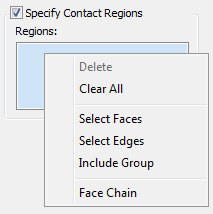
- Face Chain: When this option is activated, you can select a chain of tangent faces with a single click. The selection continues to expand until an edge is reached with no tangent face adjacent to it.
- Include Group: Click this option to access the
Include Group dialog.
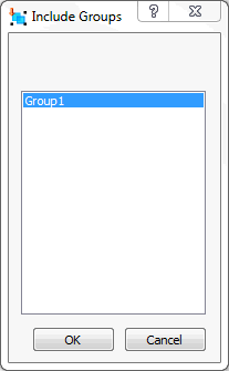
This dialog lists the Element Groups that you have created previously. Using Groups, you can limit contact generation to a portion of a larger face or edge (specifically, to particular elements along the face or edge).
 You must mesh the model before creating element groups. Then, right-click
Groups in the
Model branch (bottom half) of the Autodesk Nastran Model Tree and choose
New
You must mesh the model before creating element groups. Then, right-click
Groups in the
Model branch (bottom half) of the Autodesk Nastran Model Tree and choose
New Element Group. Select the desired elements, optionally change the
Group Name, and click
OK to create an element group. Afterwards, the group will be available for selection within the Include Groups dialog.
Element Group. Select the desired elements, optionally change the
Group Name, and click
OK to create an element group. Afterwards, the group will be available for selection within the Include Groups dialog.
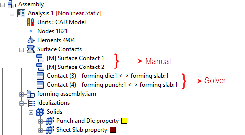
- Add To Analysis: Surface contacts generated this way can be applied to an analysis by clicking the
Add to Analysis checkbox. You can also drag and drop, or copy and paste, contact pairs from the
Model branch to the
Analysis branch of the tree.
Additionally, you can right-click Analysis, and select Add/Remove Entities from the context menu. The following dialog appears:
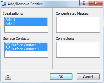
In the list under Surface Contacts, entries that were initially highlighted are already active in the current analysis. Entries that are not initially highlighted exist only in the Model branch of the tree. Click to toggle the selection state of the contact entries. When you click OK, the highlighted contact pairs will be added to the current analysis, and the non-highlighted entries will be removed from the Analysis (if they were in it). This tool will not delete contact pairs from the Model branch of the tree. In the following image, the two manual surface contact pairs that were selected in the preceding dialog have been added to the Analysis.
-
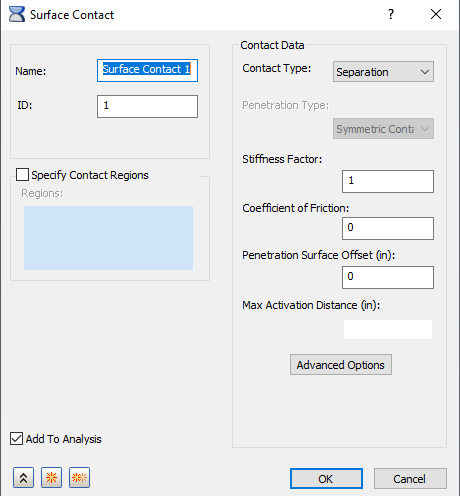
Contact Data:
- Contact Type: In this section, different types of contact can be generated and disabled. Note that the Contact Type terminology now matches Inventor Stress Simulation terminology. Moreover, when you hover over the Contact Type drop-down menu, tool tips are available to show the Nastran terminology, as you can see in the image below:
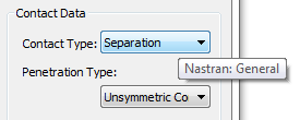
-
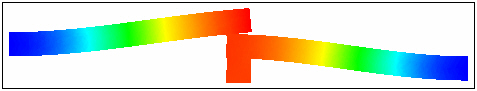
Separation
(Nastran: General)
- This type of contact is a true surface-to-surface contact. Both sliding and opening are allowed.
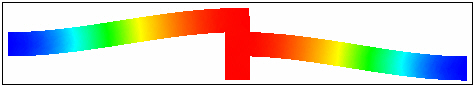
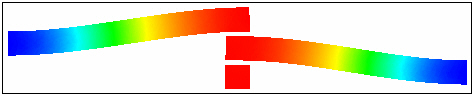
- The example in the figure below shows 3 blocks, the bottom block is pushed up and free surface contact is used between the touching surfaces.
Note: For Explicit Analysis, only Separation and Bonded contact types are supported. -
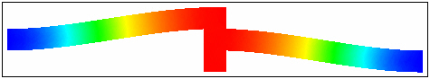
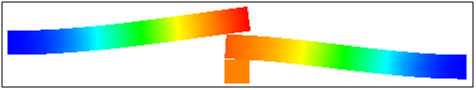
Bonded
(Nastran: Welded)
- This type of contact is used to bond the touching surfaces together. It moves together with loading.
- The advantage with this type of contact is that the mesh does not have to be the same.
- It can be useful in cases where touching surfaces on different parts have dissimilar meshes and do not undergo relative displacement. In other words the surfaces are treated to be bonded together.
- The welded contact response between the beams is shown in the figure below. It moves together as shown in the picture.
-
Sliding/No Separation
(Nastran: Slide)
- With this type of contact the element will act similar to a welded contact element in tension and compression, but will slide in-plane.
- Friction is ignored for this contact type, so contact data should not include friction settings.
- Slide contact can be used in linear and nonlinear solutions, but not in Explicit Dynamics.
-
Separation/No Sliding
(Nastran: Rough)
- With this type of contact the element will act similar to a general contact element in tension and compression, but will not permit sliding in-plane.
- If the analysis types are not nonlinear, the contact type will default to welded.
- Separation/No Sliding is not applicable to Explicit Dynamics.
-
Offset Bonded
(Nastran: Offset Weld)
- The offset weld setting is intended for welded connections with significant separation between contact surfaces.
- The offset weld setting is intended for welded connections with significant separation between contact surfaces.
-
Separation
(Nastran: General)
- Stiffness Factor: This value controls the stiffness scaling of the contact. The stiffness is automatically determined based on the adjacent stiffness.
- The higher this value, the stiffer the contact and the less the penetration, but too high a value may cause convergence issues and chatter.
- Sometimes setting this to a lower value may help convergence, but usually the default (1.0) works well for Autodesk Nastran analysis.
- Coefficient of Friction: Specify a coefficient of static friction.
- Penetration Surface Offset: Specify a penetration surface offset. This defines a numerical offset value for instances such as plate to plate or solid to plate contact.
- Max Activation Distance: This is a tolerance value that specifies the distance that contact elements should be activated. This helps limit the number of contact elements and therefore decreases solution time prevents unnecessary, and possibly conflicting, contact elements. When the box is checked and no value is specified, the default solver distance will be used. This is a large distance based upon the model size. When a value is input, the solver will use that value. When the box is unchecked the auto function will be used. Using the auto setting, the solver determines the activation distance. This is different from when the box is left blank and the default solver value is used.
- Advanced Options Set the additional solver options:
- Frictional Stiffness for Stick: Specify a frictional stiffness for stick. The value of frictional stiffness should be chosen carefully. A method of choosing a value is to divide the expected frictional strength (MU * expected normal force) by reasonable value of the relative displacement before slip occurs. A large stiffness value may cause poor convergence, while too small a value may result in reduced accuracy. An alternative method is to specify the value of relative displacement using SMAX.
- Max Allowable Penetration: This is used in the adjustment of penalty values normal to the contact plane. A positive value activates the penalty value adjustment. This is not applicable to Explicit Dynamics.
- Contact Type: In this section, different types of contact can be generated and disabled. Note that the Contact Type terminology now matches Inventor Stress Simulation terminology. Moreover, when you hover over the Contact Type drop-down menu, tool tips are available to show the Nastran terminology, as you can see in the image below: