
Description
The PCOMP entry defines the properties of an n-ply composite material laminate.
Format
| 1 | 2 | 3 | 4 | 5 | 6 | 7 | 8 | 9 | 10 |
| PCOMP | PID | Z0 | SB | FT | TREF | LAM | |||
| MID1 | T1 | THETA1 | MID2 | T2 | THETA2 | ||||
| MID3 | T3 | THETA3 | -etc.- |
Example
| PCOMP | 190 | -0.256 | 2500.0 | TSAI | |||||
| 200 | 0.065 | 0.0 | 210 | 0.04 | 45.0 | ||||
| 220 | 0.03 | 60.0 |
| Field | Definition | Type | Default |
|---|---|---|---|
| PID | Property identification number. | Integer > 0 | Required |
| Z0 | Distance from the reference plane to the bottom surface. | Real | -1/2 element thickness |
| SB | Allowable shear stress of the bonding material (allowable interlaminar shear stress). The SB parameter is required if failure index is desired. | Real > 0.0 | |
| FT | Failure theory. The following theories are allowed; if blank, no failure calculation is performed.
HILL for the Hill theory HOFF for the Hoffman theory TSAI for the Tsai-Wu theory STRESS for the maximum stress theory STRAIN for the maximum strain theory MCT for Multicontinuum theory |
Character or blank | |
| TREF | Reference temperature. See Remark 3. | Real | 0.0 |
| LAM | Laminate option. If LAM = SYM, only plies on one side of the element centerline are specified. The plies are numbered starting with 1 for the bottom layer. If an odd number of plies is desired with LAM = SYM then the center ply thickness (Ti) should be half the actual thickness. | Character or blank | If blank, all plies must be specified |
| MIDi | Material ID of the various plies. The plies are identified by serially numbering them from 1 at the bottom layer. The MID’s must refer to MAT1 or MAT8 Bulk Data entries. See Remark 6. | Integer > 0 | MID1 required; see Remark 1 |
| Ti | Thicknesses of various plies. See Remark 1. | Real or blank | T1 required |
| THETAi | Orientation angle of the longitudinal direction of each ply with the material axis of the element. (If the material angle on the element connection entry is 0.0, the material axis and side 1-2 of the element coincide.) The plies are numbered serially starting with 1 at the bottom layer. The bottom layer is defined as the surface with the largest minus Z value in the element coordinate system. | Real or blank | 0.0 |
Remarks
- The default for MID2, …, MIDn is the last defined MIDi. In the example above, MID1 is the default for MID2, MID3, and MID4. The same logic applies to Ti.
- At least one of the four values (MIDi, Ti, THETAi) must be present for a ply to exist. The minimum number of plies is one.
- TREF given on the PCOMP entry will be used for all plies of the element; it will override values supplied on material entries for individual plies. If the PCOMP references temperature dependent material properties, then TREF given on the PCOMP will be used as the temperature to determine material properties. TEMPERATURE Case Control commands are ignored for deriving the equivalent PSHELL and MAT1 entries used to describe the composite element.
- The failure index for the boundary material is calculated as Failure Index = max(τ1z , τ1z). The Failure Index for the ply is calculated as shown in the following table.
Theory Failure Index Remarks Hill 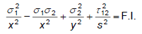
Orthotropic materials with equal strengths in tension and compression. Hoffman 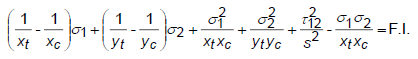
Orthotropic materials under a general state of plane stress with unequal tensile and compressive strengths. Tsai-Wu 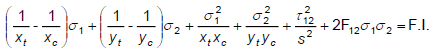
Orthotropic materials under a general state of plane stress with unequal tensile and compressive strengths. Max Stress 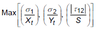
None Max Strain 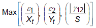
None - The STRENGTHRATIO model parameter is used to request the output of the Tsai Strength Ratio (R) instead of Failure Index. (See the Parameters section for more information on STRENGTHRATIO.)
- This entry may be used to define a layered shell element. The MIDi fields may only reference MAT1 or MAT8 entries.