For a base which houses multiple features where Line of Sight might be an issue you must calculate multiple toolpaths using different workplanes. This ensures all the features are contained within the Line of Sight of a workplane.
The following example demonstrates how you can separate your surfaces into Levels and Sets for multiple features:
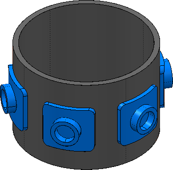
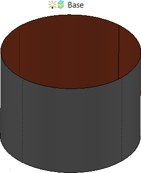
- Import your model.
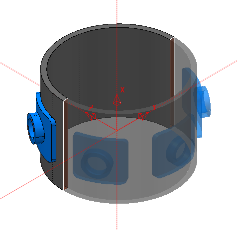
- Orient the Z-axis direction of your workplane to provide a suitable Line of Sight for a group of features.
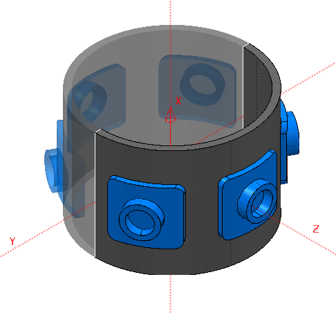
- Create another workplane and orient its Z-axis direction to capture the remaining features within its Line of Sight.
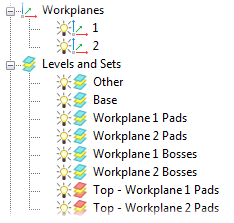
- Select the cylindrical base surface and add it to a new Level.
- Separate the surfaces of the features onto their own Levels.
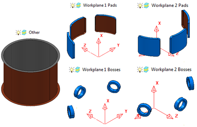
The boss features are deposited onto the pad features. This means the top pad-surfaces are used as the base surfaces for the boss-feature calculations in addition to being part of the pad-feature calculations. Therefore, these surface must be included in their own Sets.
- Create new Sets for the top pad-surfaces and add the surfaces for their appropriate workplanes to the Sets:
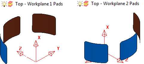
This enables you to re-use the top pad-surfaces as base surfaces for the boss features without including the wall pad-surfaces. Using an entire pad feature as a base for a boss feature could lead to the toolpath rolling over the junctions between the top and wall surfaces.
Your surfaces are now organized to calculate toolpaths for multiple features: