
The Smoothing tab on the Tool axis dialog smooths any changes in velocity or direction of the tool axis. This minimises judder on the machine tool.
This tab is only available if you select Tool axis smoothing on the Definition tab. It contains the following:
Elevation/Azimuth — Select how to smooth the elevation/azimuth angle of the tool axis. An elevation of  90
90 aligns the tool with the Z axis, and an elevation of 0 means the tool is in the XY plane. Azimuth is the angle between the
  X axis and the projection of the tool in the XY plane.
- None — Select this option to have no smoothing. The tool axis orientation moves when it needs to.
- Smoothed — Select this option to enable the tool axis angle to change smoothly over the Smoothing distance. The change in angle will not be more than the Maximum angular correction unless the angle of the unsmoothed toolpath varies by more than the Maximum angular correction in less than Smoothing distance. In such regions, the angle may change by more than the Maximum angular correction to give a smooth result.
- Stepped on surface — Select this option to enable the tool axis angle to change by up to the Maximum angular correction to form steps of constant value. To avoid sharp tool axis movements, a smooth transition between steps is made starting at the Smoothing distance away from the possible ends of adjacent steps. The tool always remains in contact with the surface.
- Stepped with links — Similar to Stepped on surface, select this option to enable the tool axis angle to change by up to Maximum angular correction to form steps of constant value. In this case, the toolpath segments are subdivided at the end of each step, and link moves are inserted so the tool axis changes when the tool is not in contact with the model. This means that tool axis angle of each toolpath segment is constant.
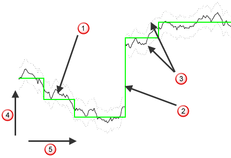
 Original toolpath, no smoothing
 Smoothed toolpath
 Maximum angular correction limits
 Azimuth or elevation
 Toolpath distance
Maximum angular correction — Enter the maximum angle the smoothed axis may deviate from the initial in the elevation direction. The maximum angular correction angle is only exceeded if the unsmoothed toolpath moves by more than this value in less than the Smoothing distance. In such regions, the angle may change by more than the Maximum angular correction to give a smooth results.
Maximum angular correction — Enter the maximum angle the smoothed axis may deviate from the initial in the azimuth direction. The maximum angular correction angle is only exceeded if the unsmoothed toolpath moves by more than this value in less than the Smoothing distance. In such regions, the angle may change by more than the Maximum angular correction to give a smooth results.
Smoothing distance — Enter the distance over which to smooth the tool axis movement. When using Stepped on Surface, or with sudden changes in direction in the original toolpath (such as a right-angled corner), you get rapid changes of orientation of the tool axis which leaves dwell marks. To prevent this, the Smoothing distance blends the change in orientation and gives a much improved surface finish.
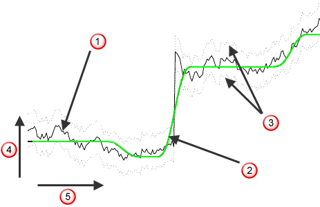
Original toolpath, no smoothing
Smoothed toolpath
Maximum angular correction limits
Azimuth or elevation
Toolpath distance
Rotary axis configuration — The read-only field displays the coordinate system PowerMill uses to define the elevation and azimuth for smoothing the tool axis, if Tool axis smoothing is selected on the strategy dialog's Tool axis page, or on the Tool Axis dialog's Definition tab. To specify which workplane PowerMill uses, select a rotary-axis-configuration option on the Machine tool page of a strategy dialog.