
The Circular tab on the Multiple Transform dialog applies multiple Rotate transformations to workplanes.
 ,
,  , or
, or  , set in the Information toolbar.
The Circular tab contains the following:
 Angle — Enter the angle between elements in the transform. You can also use the slider, or specify the Number of elements to determine the angle.
 Angle lock — Use to determine whether the rotation angle is calculated automatically or not.
- Calculated — When displayed, shows values calculated by PowerMill. This assumes that you want a full circular pattern (Angle = 360/Number).
 Edited — When displayed, shows value entered by you (or another user). Click to change this value to the automatically calculated value. The Angle and Number values operate independently. This enables you to create a partial circle rather than a full circular pattern.
 Radius — Enter the radius of the pattern. You can also use the slider to determine the radius.
Radius lock — Determines whether the rotation radius is defined automatically or not.
- Calculated — When displayed, shows values calculated by PowerMill. The radius is the distance from the centre of the rotation (defined by
 ) to the centre of the set of curves.
 - Edited — When displayed, shows value entered by you (or another user). Click to change this value to the automatically calculated value.
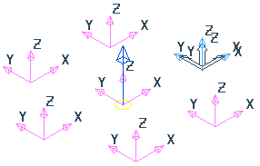
 Clockwise — Click to rotate the transform clockwise by half of the Angle. Clicking this updates the Offset angle. For example, the original transform:
Click to update the Offset angle to -45 and change it to:
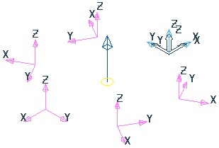
 Anticlockwise — Click to rotate the transform counter-clockwise by half of the Angle. Clicking this updates the Offset angle.
 Workplane origin — When selected, the active workplane is the origin. If no workplane is active then the global coordinate system is the origin.
 Bounding box origin — When selected, the origin is the centre of the bounding box containing all the entities.
 Move origin — When selected, you can move the origin graphically by dragging or by entering coordinates using
  ,
,  , or
, or  and
and  in the Status bar.
 Number — Enter the number of entities in the circular pattern. If the angle lock is , editing this box updates the angle. If the angle lock is , Angle and Number work independently.
Offset angle — Enter the start angle of the transform. For example:
Offset angle of0:
Offset Angle of20:
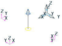
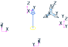
Rotation — Select whether you rotate or move the curves around the transform. For example:
 Rotate and copy:
 Rotate and move:
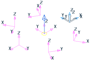
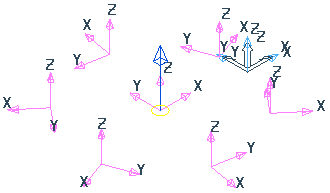
Centre element — When selected, creates an additional copy of curves at the centre of the circle. For example:
Centre element selected:
Centre element deselected:
Sorting — Defines the creation order of the new workplanes in the Explorer:
Clockwise — Creates a toolpath where the duplicated entities are machined in a clockwise direction:
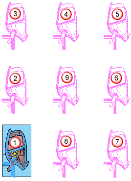
Anticlockwise — Creates a toolpath where the duplicated entities are machined in an counter-clockwise direction.
For more information, see Circular transform example. This shows how to create multiple rotations on a toolpath using a circular pattern, but the principle is the same for workplanes.