
Use the following options in the Dynamic Machine Control tab > Draw panel > Display menu to draw toolpath elements:
- Cutting Moves — Draws the toolpath cutting moves for the active toolpath.
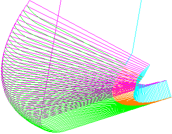
Toolpath with cutting moves, leads and links drawn:
Toolpath cutting moves not drawn:
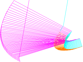
The toolpath leads and links are drawn. Not drawing the cutting moves is useful when trying to view toolpath leads or links.
- Links — Draws the links for the active toolpath.
Toolpath with cutting moves, leads and links drawn:
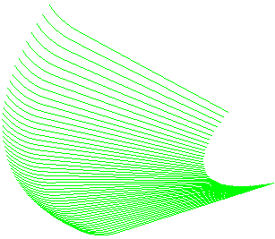
Toolpath links not drawn:
Not drawing the links is useful when trying to view toolpath cutting moves or leads.
- Leads — Draws the toolpath leads for the active toolpath.
Toolpath cutting moves and leads drawn, but toolpath links not drawn:
Toolpath links not drawn:
The toolpath leads are not drawn, but the cutting moves are. Not drawing the leads is useful when trying to view toolpath cutting moves or links.
- Orientation Normals — Draws the tool orientation vector.

If you combine this with simulating the toolpath (using Simulate from start on the individual toolpath menu),
 shows the tool orientation.
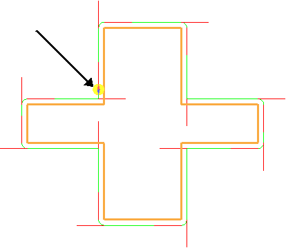
This is useful to see the contact orientation of the tool when using an asymmetric machine head.
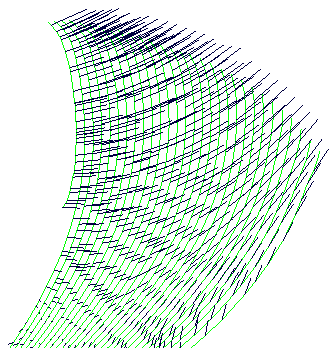
- Tool Axes — Draws the axis of the tool at each toolpath point so that you can visualise the changing tool orientation:
- Contact Normals — Draws the toolpath contact normals at each toolpath point in red.
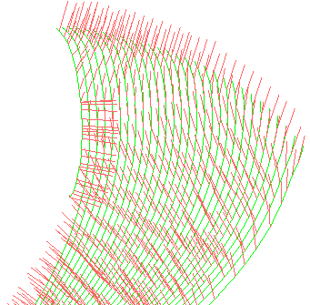
This option is available only if you select Contact Normals on the Point Distribution
 dialog. The contact normals are the I, J, K vectors.
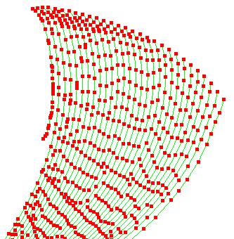
 - Points — Draws each toolpath point for the active toolpath in red, and draws the arc centres in blue. These are used for visualisation of point density.
- Contact Track — Draws the trace of the toolpath contact points in red.
This option is available only if you select Contact Normals on the Point Distribution
dialog. The contact normals are the I, J, K vectors.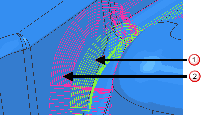
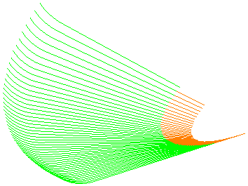
 Standard toolpath trace in green.
 Toolpath contact point trace in red.